
Service manual


SA7x Internal Cabling
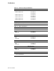
Table A–1 lists the fan connections.
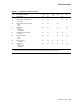
Table A–1 Fan Connections
TB2 Fan Signal Name
J1–1 J1–1 +12.6V
J1–2 J1–2 +12.6V RTN
J1–3 J1–3 Fan Control H
J1–4 J1–4 Fan Rotation H
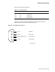
Figure A–6 shows the dc power connections for the four RA7x disk drive
connectors (P2, P3, P4, and P5) shown in Figure A–2.
Figure A–6 4-Pin DC Power Connector
4
3
2
1
+5.0V DC
GROUND
SPINDLE MOTOR RETURN
+12.0V DC
(RED WIRE)
(BLACK WIRE)
(2 BLACK WIRES)
(2 GRAY WIRES)
CXO-3524A-MC
SA7x Internal Cabling A–7