
Installation guide
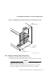
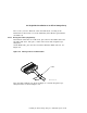


4.2 Single-Host Installation of an SF3xx Storage Array
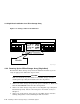
b. Check that the SPLIT indicator (behind the door of the OCP) is on for
SF3 and SF6 only.
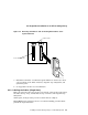
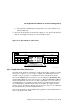
2. Press the Ready button on the OCP (see Figure 4–10). The Ready indicator
flickers, then lights steadily green once the ISE is on-line.
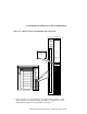
Figure 4–10 OCP Indicators and Controls
Write
Protect
Ready Fault
DSSI
ID
Write
Protect
Ready Fault
DSSI
ID
d
i g i
t
a l
SHR_X1128_89
1
2
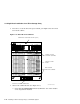
4.2.5 Single-Host Final Verification
Now that all the hardware installation, cabling and labeling, and the powering
up steps are complete, you are ready to configure the DSSI subsystem and
verify the correct operation of each ISE in the array with the host system.
Refer to the KFMSA Module Installation and User Manual (EK–KFMSA–IM)
and the TF857 Magazine Tape Subsystem Service Manual (EK–TF857–SM) for
detailed information on how to proceed with verifying the correct operation of
each ISE that has been installed. In this manual, you will find the procedure
for establishing the communications between the ISEs, the adapter module,
and the system. You will also find the step-by-step procedures for reconfiguring
the system with its newly installed DSSI devices.
Refer to the manuals for the disk ISE and tape ISE for detailed information on
the local programs in the ISEs.
Installing an SF3xx Storage Array to a VAX 6000 System 4–15