
Installation guide


4.2 Single-Host Installation of an SF3xx Storage Array
Disconnect the power cable from the source outlet. Perform the
operation, then reconnect the power cable to the source.
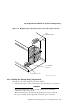
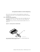
2. Connect the 108-inch DSSI cable or cables (part number BC21Q–09) from
the array DSSI I/O panel to the system I/O panel.
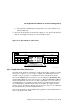
a. At the system I/O panel, remove the terminator or terminators (part
number 12–31281–01). See Figure 4–5. Store these terminators in the
ESD pouch on the rear door of the storage array cabinet.
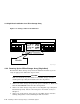
b. To determine which of the two DSSI connectors on the system I/O panel
to connect to:
• Open the system I/O panel by removing the screws that secure it to
the system chassis. Let the panel swing down to its rest position.
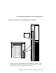
• Find the first KFMSA module installed in the system XMI
backplane. It is the KFMSA module in the lowest numbered
slot of the KFMSA modules installed.
• Follow the cabling from the backplane to the system I/O panel.
• While viewing the front of the I/O panel, note that the DSSI
connector on the right is KFMSA DSSI bus 1 and on the left is
bus 2.
• For port 1 and 3 on the SF3xx I/O panel, connect the 108-inch DSSI
cable to the right DSSI connector of the system I/O panel.
• For port 2 and 4 on the SF3xx I/O panel, connect the 108-inch DSSI
cable to the left DSSI connector of the system I/O panel.
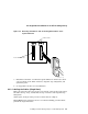
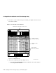
c. Install one end of the 108-inch DSSI cable (part number BC21Q–09) to
one of the ports on I/O panel at the bottom rear of the system cabinet.
See Figure 4–5.
• Connect the DSSI cable from the DSSI port 1 (of the I/O panel) to
the first DSSI connector of the first KFMSA bulkhead connector on
the system I/O panel.
• Connect the DSSI cable from the DSSI port 2 (of the I/O panel) to
the second DSSI connector of the first KFMSA bulkhead connector
on the system I/O panel.
4–8 Installing an SF3xx Storage Array to a VAX 6000 System