
Installation guide

C.2 Conversion Procedure
4. Press each drive dc power switch for each Sx72 storage enclosure. Start
with position 1 and continue in numerical order.
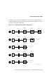
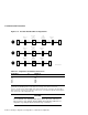
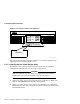
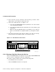
5. Observe the OCP indicators. See Figure C–12.
a. Check that the TERM PWR indicator (behind the door of the OCP) is
on for all positions installed.
b. Check that the SPLIT indicator (behind the door of the OCP) is off for
all positions.
c. Make sure that all DSSI ID switches on all OCPs are set to left-rear
(ID = 1), left-front (ID = 2), right-front (ID = 3), and right-rear (ID =
4).
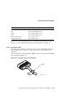
6. Press the Ready button on the OCP. See Figure C–12. The green Ready
indicator flickers, then lights steadily once the ISE is on-line.
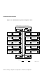
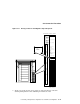
Figure C–12 OCP Indicators and Controls
Write
Protect
Ready Fault
DSSI
ID
Write
Protect
Ready Fault
DSSI
ID
d
i g i
t
a l
SHR_X1128_89
1
2
C.2.6 Bringing a Dual-Host Conversion On-Line
Refer to the KFMSA Module Installation and User Manual (EK–KFMSA–IM)
for the section on configuring a dual-host configuration.
Note that you will be instructed to perform the following tasks:
• Boot VAX/DS on the host systems.
• Attach the KFMSA modules in each system.
C–18 Converting a Single-Host Configuration to a Dual-Host Configuration