
Owners Manual


1) To Open: Disconnect the AC Power cable, let sit 15 minutes to allow the power supply capacitors to discharge. Remember
there are high voltages (350VDC) used in the SLAM! and that the capacitors may continue to hold a charge after AC power
and/or power supply connector is removed - Remove the two Philips Machine screws located on the perforated top cover
(towards the back). Slide the top cover out towards the back. There are 3 LEDS located towards the back and center. They
indicate capacitor charge. If one is lit , wait for full discharge and the LED to completely go out, and then it is safe.
BE CAREFUL! We suggest using gloves and/or "one hand only" when the top is off when working on tube gear.
2) Replacing Tubes: The tubes are marked as to their type 12AT7 (for voltage gain) and 6414 (for line drivers). Another
warning: Tubes get HOT. Let them cool before you attempt to touch them. Wiggle the tube back and forth as you pull it up.
If you suspect a tube, you can swap it with the other channel. If the problem follows the tube, you were right, it is that tube. If
not, try swapping another pair of tubes. It is a good idea to have a few spare tubes for emergencies as this will fix better than
90% of most problems.
3) Trim Procedures. This is best done by a trained technician with access to specialized instruments like voltmeters and
distortion analysers. Replacing a tube generally does not require a re-calibration. Without a distortion analyser, we suggest 'no
touchy' the trims marked THD and BAL. The full factory calibration procedure is on the following page.
4) Changing JUMPERS: There are 5 jumpers that allow for a little bit of user modification. The first is in the center and on
the left side of the SideChain board. With this jumper IN (factory set), when STEREO LINK is selected, only the left side
controls are active and are operating on a summed L&R (mono) signal. With no jumper here, both STEREO LINK and BOTH
& EXT use both sets of controls. This mode is a similar to previous Manley compressors, best for mastering, but inconvenient.
The second pair of jumpers is for 'Advanced Mode'. The factory sets these to connect PARA and TRANS which allows you
to plug into the 1/4" UNBALANCED OUTPUT and NOT disconnect the transformer, A to D converter and XLR output. If
the jumper is set to connect BREAK and TRANS, the 1/4" output completely bypasses the transformer, A to D and XLR output.
Then the XLR output can be used as an input to the A to D which allows you to insert an EQ (etc) between the 1/4" output and
the A to D input. A pair of 1/4" to XLR male and pair of 1/4" to XLR female will usually be the easiest way to patch this.
The third pair of jumpers are a grounding option and set whether the XLR outputs are PIN 1 grounded to Circuit Ground or
Chassis Ground. These are factory wired for Chassis Ground, so that hum current is dumped to chassis. The XLR inputs are
wired for Pin 1 = Circuit Ground because the Phantom Power return is carried on Pin 1 or ground reference.
5) Replacing Meter Bulbs: New units like this use very long-life LEDS. For older units lamps are available from Manley (12
volt Festoon) and available from Selco part number 19-29-39/12V. You remove the two small Phillips screws (back, top, center)
which allows you pull the white light cover panel away. Gently pry out the old bulb, insert the new one and screw the panel
back on. Note that a few of the very first units used 26V lamps and if in doubt, the volts are marked on the bulb.
21
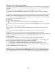
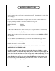
THE GUTS
SIDECHAIN BOARD
6414
6414
12AT7
12AT7
LED LOGIC
CONTROL BOARD T&B CONTROL BOARD T&B
XLRPIN 1
CIRCUITGND
CHASSISGND
TRANS
PARA
BREAK
BREAK
PARA
CHASSISGND
XLRPIN 1
CIRCUITGND
TRANS
STEREO LINK=
LEFT SIDE(SUM)
MIC THD
OP THD
OP GAIN
OP THD
OP GAIN
MIC THD
FET
BIAS
BAL
GR
FET
ZERO
METER
OPTO GR
OPTO GR
METER
ZERO
FET METER
AUDIO PEAK
FET METER
AUDIO PEAK
BIAS
BAL
GR
LINE
TRANSFORMER
LINE
TRANSFORMER
FETGR
TRANSFORMER
FETGR
TRANSFORMER
MIC
TRANSFORMER
MIC
TRANSFORMER
-18V
+18V
+18V
-18V
5V A
5V D
3.3V D
BAL LINE OP
TRANSFORMER
30uF/200V
MULTICAP
BAL LINE OP
TRANSFORMER
30uF/200V
MULTICAP
300V LED
VU LAMP
26V / 1W
.95" x .25"
VU LAMP
26V / 1W
.95" x .25"
CHASSIS GND
CIRCUIT GND
+/-18V LED
5V LED
AUDIO
SIDE CHAIN
REMOVE THESE
2 SCREWS. TOP
SLIDES BACK
22K
140-180VDC
22K
140-180VDC
ANAGRAM QUANTUM
DIGITAL CONVERTER
DAC AMPS
REMOVE THIS JUMPER
BEFORE INSTALLING A/D/A