MANLEY SLAM! Stereo Limiter And Micpre OWNER’S MANUAL rev3/11/11cd
CONTENTS SECTION PAGE INTRODUCTION 3 POWER SUPPLY 5 BACK PANEL & CONNECTING 6 FRONT PANEL 8 METERING 10 LIMITERS, HINTS, ETC.
INTRODUCTION THANK YOU!... for choosing the Manley SLAM!. This unit combines Mic and Instrument Preamps, 4 limiters, comprehensive metering and is ready for or already has the digital converter option. As one might expect, the basic operations are fairly simple and instructions may not be needed - but - the SLAM! has a lot of advanced features, and we strongly recommend reading through the manual. There are a lot of tricks and features that are not so obvious.
The Swiss Army Knife 3) This is a limiter and limiters generally can create weird distortions especially when the gain reduction is deep and releases are fast. The SLAM! FET limiter has very fast releases so it can be dangerous. The OPTO is easier to use because the attack & release are slower which is why opto’s have always been popular. Sometimes we want the ease of opto and the speed of FET, and using the FET gently to ‘clean up’ the overshoots of the opto is pretty easy too.
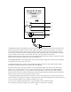
MANLEY SLAM! POWER SUPPLY UNIT WARNING: to reduce the risk of fire or electric shock, do not expose this unit to rain or moisture. CAUTION: risk of electric shock. do not open, high voltage. refer all servicing to qualified personnel only N9512423 line voltage switch 5 replace fuse with same 4 type and rating FUSE 3 ON 2 POWER 1 1) POWER MULTI-PIN: 16 PIN AMP connector that screws into the matching socket on the back of the SLAM!. This should be connected first.
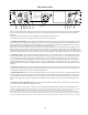
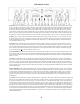
THE BACK PANEL INSTRUMENT TRANSFORMER INSERT FET SC INSERT OPTO SC CHASSIS BALANCED OUTPUT UNBAL OUTPUT GROUND SEND SEND EXT LINK (5.1) EXT LINK (5.1 etc) SC MIX I/P OPTO SC MIX I/P FET IN =100K OHM 1/2 IN =10 MEG PHANTOM POWER 48V OFF MUTE MONITORS THEN PULL TOTOGGLE RTN TRANSFORMER BALANCED OUTPUT SERIALNUMBER UNBAL OUTPUT 1/4” BYPASSES XLR O/P. XLR DRIVES ADC DRIVES ADC DESIGNED BY HUTCH ANAGRAM TECHNOLOGIES, JERRY GARSZVA, E. MANLEY M. MARGOLIS, B.
6) PHANTOM POWER SWITCH: This simply turns on 48 regulated volts of phantom power that ‘rides’ on Pin 2&3 of the BALANCED XLR INPUT. In this case, it is also only ON when you select one of the 3 Mic modes on the SOURCE switch.
THE FRONT PANEL 1)SOURCE: This is the Input Selector that you use to choose the input to the SLAM!. The choices are LINE, DI, MIC, MIC ø (phase reverse), and MIC 100 HZ (high pass filter) which has a little graphic showing the filter. LINE selects the BALANCED LINE INPUT Combo jack (XLR or 1/4”) and is intended for +4 dBu signals, but by cranking the INPUT level can be used with -10 dBv signals. DI selects the INSTRUMENT INPUT jack and routes it through the mic preamp for lots of gain if needed.
8) RELEASE: This only affects the FET Limiter. There are 11 positions numbered from 2 Seconds (slowest), to 10 milli-Seconds (fastest). Slow releases tend to be the least audible and will be cleanest. Medium release times on the SLAM! are pretty fast for a limiter and where the most loudness increase tends to be, but if pushed too far also might be obvious with pumping or a volume rise after the ‘cresendo’.
METERING The SLAM! has some very comprehensive metering. If you skip this section, you’ll be back here with the yellow highlighter pen, once you start really using the box. There are both LED bar graphs and standard VU meters, and each can show a variety of information. Before proceeding further, we should mention that any peak meters and VU meters should look different with music and that they are intended for different purposes.
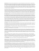
MODE1 SELECT MENU DISPLAY MODE 1PEAK Toggle Middle Combination PEAK + FET GR MODE 1GR Toggle UP Combination OPTO + FET GR +21 -1 -2 -3 -4 -5 -6 +16 -11 +26 INFINITE TIMED 1 SEC.
VU METERS Two toggles are used for the VU meters. One is used to select whether the VUs display Input Level (after the Input Pot), Output Level, or the OPTO Limiter Gain Reduction. If in BYPASS the OPTO GR the meters drop out rather than sit on zero. A VU meter showing OPTO GR seems to be a bit of a standard and the time constants and ballistics are a good match, even if the VU does not show every drop of gain reduction. The LED meter also can display Opto GR or the total gain reduction.
LIMITERS “The FET Limiter” The first compressors we know of used special tubes designed for radio and gain control. These are the “remote cut-off” type like the 6386 as used in the Fairchild 670. Manley has been making the Variable Mu® compressor/limiter for many years based on the same principle. Because we couldn’t improve much on our old opto circuit we decided to add a second ‘type’ of limiter with its own characteristics and its own historical roots.
‘Hyper-Compression’ The word ‘Hyper-compression’ is a word mastering engineers use and was coined by Lynn Fuston (Mastering Web Board, DSD vs 96/24). For many people it implies the idea of limiting and multi-band limiting and normalizing and squeezing every last drop of apparent volume possible onto a stereo mix but most mastering engineers would prefer not to. It has become almost a contest and everybody wants to be louder than everybody else.
Which brings up the first thing last. The traditional way to have loudness, dynamics, excitement and smoothness all at the same time is with that old tool called ‘arranging’. Take another listen to your favorite records and check out how they use many instruments to create loud or a few to create quiet or a relief. Listen to how solos & intro instruments sound great when not covered by everything else.
Limiting and more limiting and more... The following is a small section of the Orban Optimod-FM, 8400 owner’s manual. This is a compressor used by radio stations before they broadcast the music signal. Orban is, by far, the leading company building broadcast limiters in the world. This eloquent piece posted on by Robert Orban serves as yet another warning for those that intend to use hyper-compression on their mix.
THE GUTS CIRCUIT GND XLR PIN 1 CHASSIS GND REMOVE THESE 2 SCREWS.
SLAM! FACTORY ALIGNMENT PROCEDURE Prep: 1) +4 dBu (1.23vAC), 1kHZ Oscillator fed into XLR LINE INPUTS 2) UNBALANCED LINE OUTPUTS feed Level & Distortion Analyzer. 3) Select LINE on SOURCE, L&R LIMITERS off, Phantom OFF. 4) Set INPUT & OUTPUT LEVELS for 12:00. 5) Set ELOP LIMITER & FET LIMITER fully CW. 6) Set SC HZ to FLAT, ATTACK to .1 SECOND. 7) Set LINK to DUAL MONO (off). 8) Set LED to PEAK, VU to I/P, VU to 0dB. Power 1) POWER UP supply toggle – verify zero AC amps on external Variac current meter.
Limiter Trims OPTO LIMITER +4 dBu (1.23vAC), 1kHZ Oscillator fed into XLR LINE INPUTS. 1) VU select = GR. Verify reading close to 0 VU. 2) L&R LIMIT = ON. 3) Verify VU’s within 3 dB of zero. Trim ZERO VU GR on Side-chain board so that VU = 0 with no gain reduction. 4) VU select = O/P. Set ELOP LIMIT threshold knob to 9:00 O’clock. VU’s should show some reduction. 5) Adjust OPTO GR trim for 4 dB of limiting. 6) VU mode = GR. Adjust opto METER GR trim also for -4 dB displayed on VU’s.
LED Meter Trims (This is done in MODE 2) 1) With 0VU, adjust AUDIO PEAK trim (sidechain board) for 4 segments lit. Increase oscillator by 6 dB & Be sure L&R are even. Verify 10 segments lit (4th dot from top), adjust AUDIO PEAK trim if needed. 2) Kill oscillator verify no segments lit. Verify -20 dB in lights the first segment. 3) Set LED to GR. With FET LIMIT at 9:00 adjust for 4 Yellow segments lit. Be Sure L&R are even. 4) Use music to verify display is nice, balanced and no segments are dead.
TROUBLE SHOOTING There are a number of possible symptoms of something not quite right, some may be interfacing, others we will touch on as well. If you suspect a problem the following paragraphs should help. NO POWER, NO INDICATORS, NADA - Probably something to do with AC power. Is it plugged in? Check the fuse on the back panel. A blown fuse often looks blackened inside or the little wire inside looks broken or its resistance measures higher than 2 ohms.
IT MAKES NOISES WHEN THE FRONT PANEL IS TAPPED - An easy one. Some tubes become microphonic over time. That means they start acting like a bad microphone. Vibration has caused the supports for the little parts in the tube to loosen and now the tube is sensitive to vibration. Easy - Replace the tube. Which one? The one that makes the most noise when you tap it. Usually this will be one of the smaller (gain stage) tubes (12AT7A) closest to the front.
MAINS CONNECTIONS Your SLAM! has been factory set to the correct mains voltage for your country. The voltage setting is marked on the serial badge, located on the rear panel. Check that this complies with your local supply. Export units for certain markets have a moulded mains plug fitted to comply with local requirements.
SPECIFICATIONS Input Tubes: 2 x 12AT7A NOS GE specially selected by Manley Labs for lo-noise and stable bias Output Tubes: 2 x 6414W NOS USA dual triodes I/O: MANLEY transformer coupled Balanced Inputs and Outputs Micpre: Selectable 48V phantom power and PHASE REVERSE Gain: 60dB max Micpre, 43dB max DI, 20dB max Limiter Gain Input Impedance: 2000Ω Micpre, 1MegΩ DI FET Limiter: Attack: approx.
ADDENDUM FOR SLAM! MASTERING VERSION The mastering version has a number of changes compared to the regular SLAM!: 1) There are no mic preamps or instrument inputs. Instead the tube sections are paralleled for lower noise and distortion. 2) All pots are replaced with rotary switches for detented resettability and easier cal. 3) The mastering version has a true hard-wire bypass function, which is not possible on the regular version with mic preamps, etc.
The 50% setting mixes some raw input with the post limiter signal, which is often difficult in a mastering environment. Because the FET side-chain senses right off the output XLR, one immediate indication is significantly deeper gain reduction shown on the LED ladder, but less apparent limiting to our ears. In some ways, it is like reducing the ratio and threshold, maintaining a similar output level.
A few points inspired by some of the early comments from SLAM! users make it into this addendum too. The SLAM! is designed primarily as an old school text book limiter and as such the Output Level knob is not after the final FET limiter. The idea is to set the peak-stop threshold and adjust the incoming level, which is why the level controls are larger.