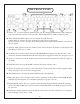
CONTENTS INTRODUCTION....................................................................................................................................3 MAINS CONNECTIONS........................................................................................................................4 THE FRONT PANEL...............................................................................................................................5 SIGNAL FLOW...............................................................
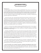
INTRODUCTION THANK YOU!… …for purchasing the Manley Laboratories Mastering BACKBONE. This product is the culmination of many custom Manley mastering consoles and mastering processors we have built over the years. When we started building custom consoles in 1990 the only option for mastering houses was to commission purpose-built systems from rare engineering shops like ours.
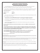
MAINS CONNECTIONS Your BACKBONE has been factory set to the correct mains voltage for your country. The voltage setting is marked on the serial badge, located on the rear panel. Check that this complies with your local supply. Export units for certain markets have a moulded mains plug fitted to comply with local requirements.
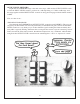
THE FRONT PANEL A. INPUT 1, 2, 3: Choose which of the three inputs will drive the BACKBONE audio chain. Whichever source is selcted here will also come out of the “SELECTED INPUT” XLRs on the back panel. B. LEFT-RIGHT REVERSE: Allows you to swap left and right channels. GAINS: When lit, engages all active electronics for the input and output gains. LØ RØ (polarity reverse): Changes the absolute polarity of the signal on both channels. For more on this, see page 6. C.
SIGNAL FLOW INPUT SELECTION The signal-flow through the BACKBONE is simple enough to describe and mostly follows the front panel left-to-right layout. Three pairs of XLRs on the back panel are balanced line inputs associated with the client’s sources. Typical sources might be a superb DAC (or two) or an analog tape machine. Next come a pair of XLRs that are direct outputs of the chosen input.
Generally the INPUT and OUTPUT LEVELS are meant to correct for any losses or unintentional gains from the source machines or in any of the outboard processing gear. However, these controls really open a lot of possibilities in terms of driving gear hotter or softer especially when one considers combining that concept with setting up outboard gain settings away from a standard unity gain setting.
INSERTS 4 & 5…SWAP! INSERT 4 and INSERT 5 are also special. You can reverse the order of these two using the button below marked SWAP. With the button pushed, Insert 5 precedes Insert 4. Whatever processors you choose for these inserts, verify that with both units NOT bypassed and “flat” (e.g. zero compression), that there are no unwanted effects related to the patch order, including other processors potentially in the chain (especially Inserts 3 and 6 which are nearest 4 & 5).
OUTPUT LEVEL SWITCHES Right after the FADER/MIX stage is the final active stage, which are the OUTPUT LEVEL switches. Like the INPUT LEVEL switches, you have 24 ½ dB steps filling a -5.5 dB to +6dB range. And this stage together with the INPUT LEVEL controls can be bypassed/engaged with the button marked GAINS. Now, it’s time for an... *IMPORTANT PARAGRAPH* Note that both the FADER/MIX and OUTPUT LEVEL controls precede INSERT 8.
THE BACK PANEL Top drawing: ELCO configuration A B Bottom drawing: DB-25 configuration MIX INPUT L SELECTED INPUT L MIX INPUT R SELECTED INPUT R C D E F INSERTS 7&8 INSERTS 5&6 G INSERTS 3&4 H I INSERTS 1&2 A. Power Switch: Where the IEC power cable is inserted, the fuse is placed, and the power is switched off and on. Most users should be familiar with this feature set. B.
BACK PANEL As previously described, you have 3 Input XLRs per side followed by an Output XLR that reflects the chosen input. These are factory set-up as AC coupled (the inputs are protected by capacitors, which may prevent some clicks or pops when switching), which implies the signal has to flow through capacitors. If these capacitors are unwanted, there are jumpers (no soldering required) to bypass them and provide DC coupled inputs (similar jumpers exist for the outputs).
THE GUTZ GUTZ There is a 4-deck sandwich arrangement of printed circuit boards that make up the active electronics that process audio. Two long boards are so-called motherboards that hold 5 small PCBs each. There are separate motherboards for left and right, and the left is the top board, while the bottom takes care of the right. Each mother has about 36 relays and a dozen connectors, plus about 4 ICs that feed a fake signal to bypassed inserts.
SOME THOUGHTS FROM OUR LAB **NOTE** We recommend leaving one rack space open above and below your BACKBONE for cooling purposes (as opposed to cooling porpoises, which we don’t know anything about). It’s always good to keep some air flowing around your gear. This helps avoid damage to delicate components, as well as to your delicate hands. GEAR SEQUENCE One interesting quality of much analog equipment is the optimum sequence of gear.
“WIDTH” cont’d... So we’ve all heard some “big” sounds before that result from mid-side tweaks. But did you know this? Let’s say you increase the width by just 1 dB (which is pretty subtle). What begins with maybe 100 dB dB of separation between left and right diminishes quickly. Now a sound that was panned hard left will also be on the right side but out-of-phase and down about -20 dB. So, what seems only a hair wider actually reduced left-right separation from 100 dB to 20 dB.
MORE ON THE MIX/FADE KNOB Traditionally, mastering engineers used a mix function when cross-fades between two analog tape machines were used to segue between songs. Now that is much easier done in the workstation. But in recent years, with the availability of convolution reverb programs and sizable libraries of impulse responses (IRs) on the internet, some mastering engineers are finding that a touch of convolution reverb helps gel drier mixes.
EXPLORING OTHER USES We’ve had a few interesting questions regarding different applications of the BACKBONE. Some customers have decided it would make an excellent teaching tool. The ability to simply and easily demonstrate the importance of gear sequence (especially when making use of the SWAP button) makes the BACKBONE well-suited for educational purposes. Still others are planning to use their BACKBONE for tracking needs, rather than the mastering applications for which it was designed.
TROUBLESHOOTING NO POWER, NO LIGHTS, NADA - Probably something to do with AC power. Is it plugged in? Is the mains voltage set correctly for your country? Also, check the fuse on the back panel. A blown fuse often looks blackened inside or the little wire inside looks broken. A very blackened fuse is a big hint that a Very Bad Thing occured. Try replacing the fuse with a good one of the same value and size. If it blows too then prepare to send the unit back to the dealer or factory for repair.
BON 18 ELCO / EDAC Version BON B I R T RIGH RIB LEFT Move these Ribbons to any Pair of Headers (INSERTS 1-8).
ELCO PINOUT This diagram is drawn from the perspective of OUTSIDE THE UNIT, looking AT THE BACK PANEL.
DB-25 PINOUT INSERTS 1 & 2 RETURN 1-L RETURN 2-L RETURN 1-R RETURN 2-R SEND 1-L SEND 2-L SEND 1-R SEND 2-R HOT COLD GROUND HOT COLD GROUND HOT COLD GROUND HOT COLD GROUND HOT COLD GROUND 24 12 25 HOT COLD GROUND HOT COLD GROUND HOT COLD GROUND 4 17 5 GROUND INSERTS 3 & 4 RETURN 3-L 10 23 11 RETURN 4-L 21 9 22 RETURN 3-R 7 20 8 RETURN 4-R 18 6 19 SEND 3-L SEND 4-L 15 3 16 SEND 3-R 1 14 2 SEND 4-R 13 RETURN 5-L RETURN 6-L RETURN 5-R RETURN 6-R SEND 5-L SEND 6-L SEND 5-R SEND 6-R HOT COLD
Y-CABLE DIAGRAM Note that the Y-cable coming from the SUM output should be wired differently from the Y-cable coming from the DIFF output.
PARALLEL PROCESSING DIAGRAMS One term you may have heard over the years is “parallel processing” - but what exactly IS that, you may ask? When you duplicate a signal path and modify the duplicate in some way (compress it, add reverb to it, EQ it, or use any sort of processing), then mix it back in with the original, THAT is parallel processing. It allows you to add an effected sound to a mix (or a submix, or a single track) without losing the character or dynamic range of the original mix.
DC-COUPLING I/O MODIFICATION Your Manley BACKBONE left the factory with AC-coupled inputs and outputs. The coupling capacitors in this circuit serve to prevent any pops and clicks that might occur when changing inputs or selecting inserts. We at Manley don’t believe that these high-quality capacitors have much (if any) noticeable effect on audio passing through the BACKBONE, but some purists may disagree. We’ve designed the unit so that these capacitors can be bypassed easily, with no soldering required.
SPECIFICATIONS Frequency response……………................……. +/- 0.1 dB, 10Hz-100KHz THD + Noise………………................………... 0.0015% @ +4 dBu input level 0.0011% @ +22 dBu input level IMD60 4:1…………………………................... 0.0017% @ +4 dBu input level 0.0035% @ +22 dBu input level Crosstalk Rejection………………................…. ≥ 95dB @ 1 KHz between Gains and Mix-Fade Stages ≥ 70db @ 1KHz at SUM-DIF Stage Common Mode Rejection 100Hz……………………….............………≥ 100dB 1KHz…………………………….........
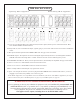
Notes: SETTINGS TEMPLATE