MANLEY LABORATORIES, INC.
CONTENTS SECTION PAGE INTRODUCTION 3 MAINSCONNECTIONS 4 CONNECTINGYOURAMPLIFIER 5 FIGURE 1 FRONTPANEL 6 FIGURE 2 TOPPANEL 7 FIGURE 3 REARPANEL 8 BIASPROCEDURES 9 OPERATIONALNOTES 10 SPECIFICATIONS 11 WARRANTY 12 WARRANTYREGISTRATION 13 NOTES 14
INTRODUCTION THANK YOU!... for choosing the Manley Laboratories Studio Standard 350 watt monoblock amplifiers. Designed around the concept that less is more, the Studio Standard 350 uses the best available parts with the shortest, cleanest, signal path possible. With the use of our own C.N.C. milling machine, we can provide you with a superb sounding machine with elegant packaging.
MAINS CONNECTIONS The Manley Laboratories Studio Reference 350 watt monoblocks requires a significant amount of AC current to operate properly. For best operation, plug the amplifier directly into the wall outlet, avoiding extension cords and other devices which restrict the current supply to amplifier. If extension cables are required, be certain that they are high quality, heavy duty (14-12 guage) cables. Your amplifier has been factory set to the correct mains voltage for your country.
CONNECTING YOUR AMPLIFIER Setting up your amplifier is rather easy. 1. Connect all source components (turntable, CD, Tuner, Tape DAT, etc.) to your preamplifier. 2. Connect the interconnects from the output of the preamplifier or switching center to RCA input. 3. Connect the hot or "+" speaker cable to the top binding post and the common or "-" speaker cable to the bottom binding post (See diagarm III). Ensure that the other end of the cable is connected correctly to the speaker.
BIAS PROCEDURES The Manley Studio Standard 350 is a fixed bias system that requires very little attention. If you wish to adjust or check the bias, follow the following steps. 1. On diagram 1, which depicts the front panel of the Manley 350, you can see two measurement tip jacks labled "READ BIAS". Place the probes of a standard volt meter in these sockets and set the volt meter to read 'millivolts'. 2. Directly below these tip jacks is a knob labeled with sixteen points.
OPERATIONAL NOTES SWITCHING ON The power switch is located on the lower right hand corner of the front panel. Push the top of the rocker switch (1) to turn on the amplifier and the bottom of the rocker to turn off the amplifier. With monoblocks we suggest that you turn on one amplifier first allowing about thirty seconds to pass before powering the other one. Also, ALWAYS turn ON your preamplifier or consule FIRST and let this settle before turning on the amplifiers.
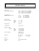
SPECIFICATIONS Vacuum Tubes: 8 x 6550, 1 x 6350, 1x 12AT7 Output Power 20 Hz - 20 KHz, 4 Ohm Load 380 W 3%T.H.D. feedback MAXIMUM 376 W 3%T.H.D. feedback STANDARD 360 W 3%T.H.D. feedback MINIMUM Slope Adjustment 20 KHz, (Ref. to 0dB @ 1K) Input Sensitivity Full power, feedback +1 dB +0.97 dB +0.88 dB MAX STAND MIN 1.8 1.44 1.2 slope = MINIMUM slope = STANDARD slope = MAXIMUM Vrms Vrms Vrms Input Impedance 82 Kohm Load Impedance 5 ohm / 2.5 ohm S/N Ratio @350W feedback MIN. STAND. MAX -90.
WARRANTY All Manley Laboratories equipment is covered by a limited warranty against defects in materials and workmanship for a period of 90 days from date of purchase to the original purchaser only. A further optional limited 5 year warranty is available to the original purchaser upon proper registration of ownership within 30 days of date of first purchase.
WARRANTY REGISTRATION We ask that you please fill out this registration form and send the bottom half to: MANLEY LABORATORIES REGISTRATION DEPARTMENT 13880 MAGNOLIA AVE. CHINO CA, 91710 Registration entitles you to product support, full warrenty benefits, and notice of product enhancements and upgrades. You MUST complete and return the following to validate your warranty and registration. Thank you again for choosing to use Manley Laboratories. MODEL ____________________ SERIAL No.
NOTES