
User Manual
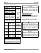
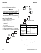
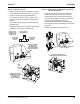
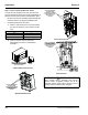
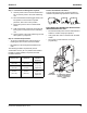
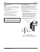
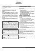
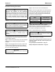
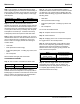
Table Of Contents
- Section 1 General Information
- Section 2 Installation
- Section 3 Operation
- Section 4 Maintenance
- Section 5 Customer Support
- Blank Page

Section 2 Installation
Part Number 000006505 Rev02 12/19 15
Step 7 Leak Check The Refrigeration System
A. Connect power to the ice machine head section -
Do not connect power to the CVD condensing
unit.
B. Place the ICE/OFF/CLEAN toggle switch in the
ICE position for 60 seconds to equalize
pressures, then move to OFF position.
C. Disconnect power to the ice machine head
section.
D. Leak check lineset connections, S trap and all
factory joints in head section and condensing
unit.
E. Connect power to the CVD condensing unit and
allow system to pump down.
Step 8 Insulation Requirements
• To prevent condensation the entire suction line
including the shut-off valve must be insulated.
• All insulation must be airtight and sealed at both
ends.
The following insulation requirements prevent
condensation at 90°F (32.2°C) ambient 90% Relative
Humidity. If higher humidity is expected, increase
insulation thickness:
Suction Shut Off Valve Insulation
The pre-formed suction shut-off valve insulation is
located in the plastic bag taped to the water curtain.
.
ELECTRONIC BIN THERMOSTAT INSTRUCTIONS
IB600C/IB800C/IB1000C ONLY
• The bin thermostat probe must be rotated down to
enable ice contact and proper operation.
• Verify probe wire does not interfere with the water
curtain.
• The control is preset and does not require
programming.
Suction Line Liquid Line
Min.
Insulation
Thickness
3/4 inch
(19.1 mm)
1/2 inch
(12.7 mm)
1/2” (13 mm)
Suction Line
1/4” (7 mm)
Liquid Line
5/8 inch
(15.9 mm)
3/8 inch
(9.5 mm)
3/4 inch
(19.1 mm)
5/8 inch
(15.9 mm)
3/4” (19 mm)
Suction Line
1/4” (7 mm)
Liquid Line
FINAL
POSITION
A. REMOVE
REAR SCREW
B. LOOSEN FRONT SCREW &
ROTATE PROBE/BRACKET.
REINSTALL & TIGHTEN ALL
SCREWS