
Troubleshooting guide
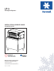


Installation and Service Manual
9
INSTALLATION
UNIT INSTALLATION
The LP-3 is shipped in a heavy duty corrugated carton with a wooden pallet. Inspect the unit for freight damage. If
any damage is noticed, stop immediately and contact your delivering freight company. You must file a freight claim
for your equipment. Failure to do so can void any claims. Manitowoc Beverage Equipment is not responsible for
any freight damage.
To properly install the LP-3, Use these guidelines:
• Meet all local code requirements.
• Have a receptacle with the proper voltage at the
installation site for connection to the LP-3. A stan-
dard 120V grounded outlet is needed for the dis-
penser. If the unit is equipped with an ice maker,
the condensing unit will need 208/230v wherever
the condenser is mounted.
• Completely unpack the LP-3, removing all padding
and shipping retainers.
• Route the beverage tubing from the syrup racks to
the location of the LP-3. Make sure to leave some
slack in each of the syrup lines in case the unit needs
to be pulled out some for service work or cleaning.
• Make all beverage connections, if necessary, at the
syrup racks.
• If installing in a counter mark the counter top with
the appropriate cut out opening.
• Check that the cut out location is approved by the
owner before any cuts are made in the counter top.
• Compare the marked cut out with the dispenser
chest size. Be sure you are going to make the proper
hole size.
• Cut the marked opening in the counter top.
• If installing in a cabinet it is recommended you per-
manently remove the lower panels for easier ser-
vice access.
• Install the legs or casters provided to the unit. Fol-
low the instructions on the cabinet to install.
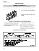
Water Connections
There are three water connections, one on the right for
the icemaker and two located on the bottom left side of
the unit that feeds all the valves for both non-carbon-
ated and carbonated water drinks.
(
See Plumbing diagram
for exact routing
). The incoming dynamic water pressure
must be at least 40 psi and no more than 55 psi. Proper
measures must be taken if the water pressure is under
or over the operating specifications. Water for the car-
bonated drinks connect at the brass carbonator pump
inlet. Water for the non-carbonated drinks connects to
the inline check valve on the inlet to the cold plate.
CO
2
Connect the CO
2
supply line. This connection is also lo-
cated at the bottom left side of the unit and is already
connected to the carbonator. The regulator for the car-
bonator should be set at 75 psi.
Syrup Connections
Make all syrup connections. These connections are lo-
cated on the bottom left side of the unit. There are ten
connections. Refer to the plumbing diagram for proper
valve selection.
Turn the power switch to on at the electrical box located
at the bottom right side of the unit.