
Troubleshooting guide


Installation and Service Manual
11
INSTALLATION
DRAINS
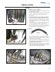
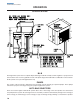
Right Side of unit as shipped:
1. During installation all drains on right side of the unit
must be properly routed.
2. Remove right side lower panel to access the drain
pan (A), icemaker (B) and auger (C) drains.
(see figure 1)
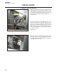
3. Route drain pan drain (A) through cut-out in base-
plate (D) and follow all national plumbing codes.
4. Route Icemaker drain (B) through cut-out in base-
plate (D) and follow all national plumbing codes.
(see figure 2)
5. Pull the insulation covering the auger drain (C) over
the clamp and fittings on the auger base (E).
6. Route auger drain (C) through cut-out in baseplate
(D) and follow all national plumbing codes.
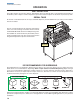
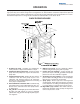
Drain Kit:
1. Attach Drain Kit (figure 3) to barbed gray drain el-
bow (F). Use worm gear clamp that is provided to
secure the hose to the barb.
2. Route the drain hose through the opening in the
LP-3 base plate (D). Follow all local & national
plumbing codes.(see figure 5)
3. Pull the insulation (G) on the drain kit over the gray
drain elbow and the CPVC drain fitting until it is flush
with the stainless steel side panel (H).
A
E
B
C
D
E
B
C
D
FIGURE 1
D
H
G
FIGURE 4 FIGURE 5
FIGURE 2
FIGURE 3
F