LP-3 Beverage/Ice Dispenser INSTALLATION & SERVICE GUIDE Part Number 5027727 Manitowoc Beverage Equipment 2100 Future Drive Sellersburg, IN 47172-1868 Tel: 812.246.7000, 800.367.4233 Fax: 812.246.9922 www.manitowocbeverage.com In accordance with our policy of continuous product development and improvement, this information is subject to change at any time without notice.
FOREWORD Manitowoc Beverage Equipment (MBE) developed this manual as a reference guide for the owner/ operator, service agent, and installer of this equipment. Please read this manual before installation or operation of the machine. A qualified service technician should perform installation and startup of this equipment, consult the Troubleshooting Guide within this manual for service assistance. If you cannot correct the service problem, call your MBE Service Agent or Distributor.
TABLE OF CONTENTS FOREWORD ........................................................................................................ 3 UNPACKING AND INSPECTION ......................................................................... 3 WARRANTY INFORMATION ............................................................................... 3 SAFETY ............................................................................................................... 6 IMPORTANT SAFETY INSTRUCTIONS .......................
TABLE OF CONTENTS USER MAINTENANCE ...................................................................................... 21 HOW TO DISASSEMBLE FOR CLEANING OR MAINTENANCE .................................. 21 DAILY CLEANING .......................................................................................................... 22 MONTHLY CLEANING ................................................................................................... 23 CLEANING AND SANITIZING OF THE DISPENSER ................
Installation and Service Manual SAFETY IMPORTANT SAFETY INSTRUCTIONS Carefully read all safety messages in this manual. Learn how to operate the SV unit properly. Do not allow anyone to operate the unit without proper training and keep it in proper working condition. Unauthorized modifications to the SV may impair function and/or safety and affect the life of the unit. CARBON DIOXIDE WARNING DANGER: Carbon Dioxide (CO2) displaces oxygen.
Installation and Service Manual SAFETY GROUNDING IN STRUCTIONS WARNING: Risk of electrical shock. Connect to a properly grounded outlet only. This appliance must be grounded. In the event of malfunction or breakdown, grounding provides a path of least resistance for electric current to reduce the risk of electric shock. This appliance is equipped with a cord having an equipment-grounding conductor and a grounding plug.
Installation and Service Manual INSTALLATION PRE-INSTALLATION CHECK LIST When installing any system, first make sure the major components are available.
Installation and Service Manual INSTALLATION UNIT INSTALLATION The LP-3 is shipped in a heavy duty corrugated carton with a wooden pallet. Inspect the unit for freight damage. If any damage is noticed, stop immediately and contact your delivering freight company. You must file a freight claim for your equipment. Failure to do so can void any claims. Manitowoc Beverage Equipment is not responsible for any freight damage.
Installation and Service Manual INSTALLATION ICEMAKER REQUIREMENTS The LP-3 may be equipped with a Manitowoc® SU1024YC icemaker. Refer to the Manitowoc® Ice/Beverage Series QuietQube® Ice Machines with CVD® Technology Installation, Use and Care Manual for additional information. See also the "MANITOWOC® SU1024YC ICEMAKER" section in this manual for exploded views and parts lists. NOTE: To turn the SU1024YC ice maker on and off and put in clean mode you need to access the toggle switch. 1.
Installation and Service Manual INSTALLATION DRAINS Right Side of unit as shipped: B A C E D FIGURE 1 1. During installation all drains on right side of the unit must be properly routed. 2. Remove right side lower panel to access the drain pan (A), icemaker (B) and auger (C) drains. (see figure 1) 3. Route drain pan drain (A) through cut-out in baseplate (D) and follow all national plumbing codes. 4. Route Icemaker drain (B) through cut-out in baseplate (D) and follow all national plumbing codes.
Installation and Service Manual INSTALLATION PURGE TUBE ROUTING 1. During installation of the LP-3 the carbonator tank purge tube (A) must be properly routed to a drain. The carbonator tank purge tube (A) may be accessed by removing the front panel of the LP-3. Clip the tie strap (B) and uncoil the purge tube (A). (see figure 1) Pressure Relief Valve A B 2. Route the carbonator tank purge tube (A) to the opening beneath the ice bin drain elbow (C).
Installation and Service Manual INSTALLATION RECOMMENDED PLUMBING The plumbing diagram is printed on a white vinyl label, normally located above the inlet tubes for syrup and water, it can be accessed by removing the splash panel of the dispenser. The plumbing diagram label explains which inlet coldplate fittings supply which dispenser valves and water manifolds. NOTE: Valves are read from right to left.
Installation and Service Manual OPERATION UNIT INSPECTION Thoroughly inspect the unit upon delivery. Immediately report any damage that occurred during transportation to the delivery carrier. Request a written inspection report from a claims inspector to document any necessary claim. SERIAL TAGS At the time of installation both the LP-3 (ice and drink dispenser) and the SU1024-YC (ice maker) serial numbers must be recorded. LP-3 SERIAL TAG The LP-3 serial number may be found by removing the valve cover.
Installation and Service Manual OPERATION EQUIPMENT The LP-3 is a 10 flavor ice and beverage dispenser, with the ice storage bin located below the counter top level. A drink tower extends 19” above the counter top level. The LP-3 is designed to fit into a 42.5” wide by 30.38” deep space, and can be counter mounted (like a conventional drop-in unit), or arranged as a stand alone with cosmetic stainless panels.
Installation and Service Manual OPERATION ICE STORAGE AND DISPENSING Ice is stored in the dispenser’s bin. Ice below the stainless steel bin liner is used to cool the aluminum cold plate, at the bottom of the ice dispenser bin. Ice above the stainless steel bin liner is dispensed into the customer’s cup. Ice is transported from the bin to the ice dispense point by the paddle wheel and vertical auger.
Installation and Service Manual OPERATION SPECIFICATIONS Dimensions 44.4" X 31.1" X 57.3" (including top cover) Weight 570 lbs (with ice 870 lbs) Electrical Requirements 110 vac 60 hz 4 amps max. Water 45 to 55 psi at 3 gpm Ice Machine Options: Offered with 1000 lbs/day CVD model SU1024Y with remote condenser Drain Four 3/4" drain hoses to be routed to a floor drain Syrups 5 Standard with Equipment: Internal carbonation or ambient carbonation for commercial applications.
Installation and Service Manual OPERATION SPECIFICATIONS B-I-B The Bag-In-Box system refers to a plastic disposable bag. The B-I-B normally contains 5 gallons of syrup, however some locations offer 2 1/2 or 3 gallon B-I-B units. This plastic bag is then held inside a cardboard or other container. B-I-B systems are for post-mix applications only. PUMPS The syrup in a B-I-B system is delivered to the beverage system through gas operated pumps.
Installation and Service Manual OPERATION Your syrup location can vary depending on the volume of beverages served and ease of accessibility. Your beverage system may set in a back storage room. Configurations are almost limitless. Check the temperatures expected for the storage location. Adverse temperatures can affect the storage and quality of beverage products. It is recommended the temperature of storage location should not fall below 40o F or rise above 90o F. BACK ROOM PACKAGE 1.
Installation and Service Manual OPERATION CARBONATION The purpose of the carbonator is to take regular tap water at street water pressure (minimum 40 PSI dynamic or flowing pressure) 3/8” water line, and increase the water to beverage system pressure (usually 75 PSI). This water is then combined with the CO2 gas. Chilling the mixture before dispensing will assist in locking the carbon dioxide into the water. After dispensing, the CO2 may be unlocked from the liquid.
Installation and Service Manual USER MAINTENANCE HOW TO DISASSEMBLE FOR CLEANING OR MAINTENANCE 1. Disconnect electrical power to the unit. 2. Remove thumb screws holding plastic splash guards and stainless splash panel. 3. Remove grid and drainpan. 4. Release the plastic latches on the back of either side of the lid assembly. (see Detail A) 10. Then remove the paddle wheel pin from the hole in the agitator.
Installation and Service Manual USER MAINTENANCE DAILY CLEANING CAUTION: Use only warm soapy water to clean the exterior of the tower. Do not use solvents or other cleaning agents. Do not pour hot coffee into the drain pan. Pouring hot coffee down the drain pan can eventually crack the drain pan, especially if the drain pan is cold or still contains ice. All cleaning must meet your local health department regulations. The following cleaning instructions are provided as a guide.
Installation and Service Manual USER MAINTENANCE MONTHLY CLEANING Scheduled cleaning must be in compliance with local health codes. This cleaning schedule is a recommendation. Follow cleaning and sanitizing instructions found in the Manitowoc manual to clean and sanitize the icemaker. The LP-3 drainpan and splash panel must be removed before cleaning the icemaker. CLEANING AND SANITIZING OF THE DISPENSER Note: Sanitize the dispenser at initial start-up in addition to monthly sanitizing.
Installation and Service Manual USER MAINTENANCE BEVERAGE SYSTEM CLEANING Sanitize the beverage system at initial start-up as well as during regularly scheduled cleaning. The drain pan must be in place under soda valves, to carry away detergent and sanitizing agents that will be flushed through valves. BAG-IN-BOX SYSTEM The procedure below is for the sanitation of one syrup circuit at a time. Repeat to sanitize additional circuits.
Installation and Service Manual USER MAINTENANCE BAG-IN-BOX SYSTEM 10. Connect Bucket 3 to system. 11. Draw sanitizing solution through system until solution is dispensed. 12. Repeat step 11 until all syrup circuits contain sanitizer solution. 13. Allow sanitizer solution to remain in system for 15 minutes. 14. Remove nozzles and diffusers from beverage valves. 15.
Installation and Service Manual EXPLODED VIEWS, PARTS & DIAGRAMS 115V WIRING DIAGRAM 26
Installation and Service Manual EXPLODED VIEWS, PARTS & DIAGRAMS COVERS & PANELS NO Part# Description 1 2 3 4 5029883 020000214 020000215 020000216 CABINET GALV RH COVER ASSM LH COVER ASSM LID ASSM 27
Installation and Service Manual EXPLODED VIEWS, PARTS & DIAGRAMS SPLASH PANEL, DRAINPAN & CUBER 28 No.
Installation and Service Manual EXPLODED VIEWS, PARTS & DIAGRAMS PANELS & LID BONNET NO Part Number Description NO Part Number Description 1 2 3 4 5 6 7 8 000000246 00850809 0901001 5000888 5031260 5031525 5031550 5031590 9 10 11 12 13 14 15 16 020000141 020000144 020000145 020000207 020000213 020001321 020001323 020001328 LABEL LOGO SNOWFLAKE NUT # 4-40 HEX BRASS SCR #8X1/2" SS PH TR HD CLIP PUSH ON LENS GROMMET FINGER LABEL LOGO SERVEND LABEL ICE COVER FRONT TRIM, TOWER TRIM, TOWER LOGO BSHG BO
Installation and Service Manual EXPLODED VIEWS, PARTS & DIAGRAMS AUGER, AGITATION & DRAIN 30
Installation and Service Manual EXPLODED VIEWS, PARTS & DIAGRAMS LEGS, CARB TANK & ELECTRIC BOX No Part Number Description 1 2 3 4 5029874 5029876 5029887 5030236 MNT MOTOR 120V ELEC 120/60 TANK CARB LEG 31
Installation and Service Manual EXPLODED VIEWS, PARTS & DIAGRAMS AUGER DRIVE, VALVE MOUNT, ROCKING CHUTE, PUMP NO. Part Number Description NO.
Installation and Service Manual EXPLODED VIEWS, PARTS & DIAGRAMS 120V AUGER DRIVE 33
Installation and Service Manual EXPLODED VIEWS, PARTS & DIAGRAMS 120V CUBER RIGHT SIDE BONNET COVER NO.
Installation and Service Manual EXPLODED VIEWS, PARTS & DIAGRAMS 120V CARB PUMP & TANK ASSEMBLY No. Part Number Description 1 2 1701110 1701115 NUT 3/8"X9/16" SWIVEL FITTING Washer 3/8" Black Nylon 3 4 1701301 5009025 CLAMP OTR 1/2" 13.
Installation and Service Manual EXPLODED VIEWS, PARTS & DIAGRAMS AUGER & ROCKING CHUTE 36
Installation and Service Manual EXPLODED VIEWS, PARTS & DIAGRAMS VALVE MOUNT CAP & AGITATOR MOTOR 37
Installation and Service Manual EXPLODED VIEWS, PARTS & DIAGRAMS AUGER TRANSITION & 120V ELECTRIC BOX 38
Installation and Service Manual EXPLODED VIEWS, PARTS & DIAGRAMS BIN 39
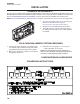
Installation and Service Manual MANITOWOC® SU1024YC ICEMAKER CONTROL BOX & EVAPORATOR COMPARTMENT 5 6 7 1, 2 10 9 SV3000 8 DESCRIPTION PART NUMBER 1 Control Board (for use with all voltages) . . . . . . . . . . . . . . . . . . . . . . . . . . . . . . . . . . . . . . . . . . . . . . 76-2782-3 2 7 mp a Fuse Mounted on Control Board. . . . . . . . . . . . . . . . . . . . . . . . . . . . . . . . . . . . . . . . . . . . . . 25-1100-3 3 Wiring Harness Control Box (Not shown) a. 115V/60 Hz/1 ph . . . . . . .
Installation and Service Manual MANITOWOC® SU1024YC ICEMAKER REFRIGERATION COMPARTMENT 8 2 5 3 6 18 19 17 16 11 1 13 14 4 14 12 10 9 7 41
Installation and Service Manual MANITOWOC® SU1024YC ICEMAKER REFRIGERATION COMPARTMENT DESCRIPTION PART NUMBER 1 Water Dump Valve a. Dump Valve Assembly without Electrical Coil . . . . . . . . . . . . . . . . . . . . . . . . . . . . . . . . . . . . . . . . . 24-0520-3 b. 115V/60 Hz Coil Only . . . . . . . . . . . . . . . . . . . . . . . . . . . . . . . . . . . . . . . . . . . . . . . . . . . . . . . . . . . 24-0521-3 c. 208/230V 50/60 Hz Coil Only . . . . . . . . . . . . . . . . . . . . . . . . . . . . . .
Installation and Service Manual MANITOWOC® SU1024YC ICEMAKER CVD1075 CONDENSING UNIT 13 14 3 16 17 19 18 22 23 21 4 12 24 11 8 5 6 10 7 9 15 PT1286A 2 1 PT1284 DESCRIPTION PART NUMBER 1 Compressor a. 208-230V/60 Hz/1 ph. . . . . . . . . . . . . . . . . . . . . . . . . . . . . . . . . . . . . . . . . . . . . . . . . . . . . . . . . . . 76-0002-3 b. 208-230V/60 Hz/3 ph. . . . . . . . . . . . . . . . . . . . . . . . . . . . . . . . . . . . . . . . . . . . . . . . . . . . . . . . . . .
Installation and Service Manual MANITOWOC® SU1024YC ICEMAKER CVD1075 CONDENSING UNIT PANELS 5 4 3 2 6 8 7 1 PT1287 DESCRIPTION PART NUMBER 1 Condenser Fan Guard . . . . . . . . . . . . . . . . . . . . . . . . . . . . . . . . . . . . . . . . . . . . . . . . . . . . . . . . . . . . . 34-0689-3 2 Control Box Cover . . . . . . . . . . . . . . . . . . . . . . . . . . . . . . . . . . . . . . . . . . . . . . . . . . . . . . . . . . . . . . . . 603477-1 3 Control Box Panel . . . . . . . . . . . . . . . . .
Installation and Service Manual TROUBLESHOOTING PROBLEM Pump will not run but tank appears to be always full. POSSIBLE CAUSE CORRECTIVE ACTION Black and/or red probe shorted Remove probes and bend straight or replace with new probe(s) Problem with motor or motor wiring Check line voltage first. Check AC voltage across load terminals on Liquid Level Control. If voltage is 120 plus or minus 10%, replace motor or motor wiring. Problem with Liquid Level Control Board. Check line voltage first.
Installation and Service Manual TROUBLESHOOTING PROBLEM POSSIBLE CAUSE CORRECTIVE ACTION Pump motor intermittent Problem with Liquid Level Control Board. Check line voltage first. If AC voltage across load terminals on Liquid Level Control Board is not 120 plus or minus 10%, replace the Liquid Level Contorl board. Pump motor starts and stops, short cycles, as soon as water level drops below Red (High) probe. Black (Low) Lead wire is open or disconnected.
Installation and Service Manual 47
Installation and Service Manual 48
Installation and Service Manual 49
INDEX A agitation ........................... 15, agitation cycle ......................... Agitator Motor ......................... Ambient ................................... Auger ........................ 21, 30, Auger Drive ............................. auger motor ............................ Auger Transition ............... 23, Auger tube ....................... 21, Auto Bag Selectors ................. 16 16 37 10 36 33 21 38 23 18 B B-I-B connectors ....................... 8 Back Room Package .....
Installation and Service Manual 51
Manitowoc Beverage Equipment 2100 Future Drive Sellersburg, IN 47172-1868 Tel: 812.246.7000, 800.367.4233 Fax: 812.246.9922 www.manitowocbeverage.com In accordance with our policy of continuous product development and improvement, this information is subject to change at any time without notice.