
Specifications
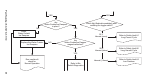


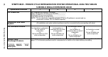
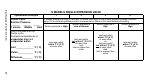
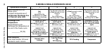
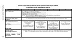

Table Of Contents
- General Information
- Installation
- Component Identification
- Maintenance
- Sequence of Operation
- Troubleshooting
- Safety Limits
- Control Board Testing
- Troubleshooting By Symptom
- Symptom #4
- Symptom #1 Ice Machine will not run
- Compressor Electrical Diagnostics
- Symptom #2 Low Production, Long Freeze
- Symptom #2 - Freeze Cycle Refrigeration System Operational Analysis Tables
- Freeze Cycle Refrigeration System Operational Analysis Table Procedures
- Before Beginning Service
- Ice Production Check
- Installation/Visual Inspection Checklist
- Water System Checklist
- Ice Formation Pattern
- Analyzing Discharge Pressure in the Freeze Cycle
- Analyzing Suction Pressure
- Single Expansion Valve Ice Machines Comparing Evaporator Inlet and Outlet Temperatures
- Multiple Expansion Valve Ice Machines Comparing Evaporator Inlet and Outlet Temperatures
- Harvest Valve Analysis
- Discharge Line Temperature Analysis
- Water Regulating Valve
- Final Analysis
- Harvest Problems
- Component Check Procedures
- Electrical Components
- Compressor Electrical Diagnostics
- Refrigeration Components
- Refrigerant Recovery/Evacuation
- System Contamination Clean-Up
- Specifications
- Charts
- Diagrams
- Wiring Diagrams
- Wiring Diagram Legend
- Wiring Diagrams Before Energy Efficient & EnergyStar Machines
- S320 Self Contained - 1 Phase
- S300/S420/S450/ S500 (after serial number 110074051) - Self Contained - 1 Phase
- S500 (before serial number 110074051) S600/S850/S1000/S1200- Self Contained- 1 Phase
- S850/S1000/S1200 - Self Contained - 3 Phase
- S500 Danfoss Compressor (after serial number 110074051) - Remote - 1 Phase
- S500 (before serial number 110074051)/ S600/S850/S1000/S1200 - Remote - 1 Phase
- S850/S1000/S1200 - Remote - 3 Phase
- S1400/S1600/S1800 - Self-Contained - 1 Phase
- S1400/S1600/S1800 - Self-Contained - 3 Phase
- S1400/S1600/S1800 - Remote - 1 Phase
- S1400/S1600/S1800 - Remote - 3 Phase
- Wiring Diagrams for Energy Efficient & EnergyStar Machines
- S300/S420/S450/S500 Self-Contained - 1 Phase
- S600/S850/S1000/S1200 Self-Contained - 1 Phase
- S850/S1000/S1200 Self-Contained - 3 Phase
- S1400/S1800 Self-Contained - 1 Phase
- S1400/S1800 Self-Contained - 3 Phase
- S3300 Water-Cooled - 3 phase
- S500 Remote - 1 Phase
- S600/S850/S1000/S1200 Remote - 1 Phase
- S850/S1000/S1200 Remote - 3 Phase
- S1400/S1800 Remote - 1 Phase
- S1400/S1800 Remote - 3 Phase
- Electronic Control Board
- Refrigeration Tubing Schematics
- Wiring Diagrams

Part Number 80-1479-3 7/10 95
PROCEDURE
Step 1 Complete the “Operation Analysis”
column.
Read down the left “Operational Analysis” column.
Perform all procedures and check all information
listed. Each item in this column has supporting
reference material to help analyze each step.
While analyzing each item separately, you may find an
“external problem” causing a good refrigerant
component to appear bad. Correct problems as they
are found. If the operational problem is found, it is not
necessary to complete the remaining procedures.
Step 2 Enter check marks (
).
Each time the actual findings of an item in the
“Operational Analysis” column matches the published
findings on the table, enter a check mark.
Example: Freeze cycle suction pressure is determined
to be low. Enter a check mark in the “low” column.
Step 3 Add the check marks listed under each of
the four columns. Note the column number with
the highest total and proceed to “Final Analysis.”
NOTE: If two columns have matching high numbers,
a procedure was not performed properly, supporting
material was not analyzed correctly or the problem
component is not covered by the analysis table.