
Specifications
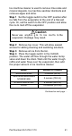
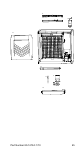
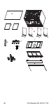
Table Of Contents
- General Information
- Installation
- Component Identification
- Maintenance
- Sequence of Operation
- Troubleshooting
- Safety Limits
- Control Board Testing
- Troubleshooting By Symptom
- Symptom #4
- Symptom #1 Ice Machine will not run
- Compressor Electrical Diagnostics
- Symptom #2 Low Production, Long Freeze
- Symptom #2 - Freeze Cycle Refrigeration System Operational Analysis Tables
- Freeze Cycle Refrigeration System Operational Analysis Table Procedures
- Before Beginning Service
- Ice Production Check
- Installation/Visual Inspection Checklist
- Water System Checklist
- Ice Formation Pattern
- Analyzing Discharge Pressure in the Freeze Cycle
- Analyzing Suction Pressure
- Single Expansion Valve Ice Machines Comparing Evaporator Inlet and Outlet Temperatures
- Multiple Expansion Valve Ice Machines Comparing Evaporator Inlet and Outlet Temperatures
- Harvest Valve Analysis
- Discharge Line Temperature Analysis
- Water Regulating Valve
- Final Analysis
- Harvest Problems
- Component Check Procedures
- Electrical Components
- Compressor Electrical Diagnostics
- Refrigeration Components
- Refrigerant Recovery/Evacuation
- System Contamination Clean-Up
- Specifications
- Charts
- Diagrams
- Wiring Diagrams
- Wiring Diagram Legend
- Wiring Diagrams Before Energy Efficient & EnergyStar Machines
- S320 Self Contained - 1 Phase
- S300/S420/S450/ S500 (after serial number 110074051) - Self Contained - 1 Phase
- S500 (before serial number 110074051) S600/S850/S1000/S1200- Self Contained- 1 Phase
- S850/S1000/S1200 - Self Contained - 3 Phase
- S500 Danfoss Compressor (after serial number 110074051) - Remote - 1 Phase
- S500 (before serial number 110074051)/ S600/S850/S1000/S1200 - Remote - 1 Phase
- S850/S1000/S1200 - Remote - 3 Phase
- S1400/S1600/S1800 - Self-Contained - 1 Phase
- S1400/S1600/S1800 - Self-Contained - 3 Phase
- S1400/S1600/S1800 - Remote - 1 Phase
- S1400/S1600/S1800 - Remote - 3 Phase
- Wiring Diagrams for Energy Efficient & EnergyStar Machines
- S300/S420/S450/S500 Self-Contained - 1 Phase
- S600/S850/S1000/S1200 Self-Contained - 1 Phase
- S850/S1000/S1200 Self-Contained - 3 Phase
- S1400/S1800 Self-Contained - 1 Phase
- S1400/S1800 Self-Contained - 3 Phase
- S3300 Water-Cooled - 3 phase
- S500 Remote - 1 Phase
- S600/S850/S1000/S1200 Remote - 1 Phase
- S850/S1000/S1200 Remote - 3 Phase
- S1400/S1800 Remote - 1 Phase
- S1400/S1800 Remote - 3 Phase
- Electronic Control Board
- Refrigeration Tubing Schematics
- Wiring Diagrams
Part Number 80-1479-3 7/10 47
F. Remove distribution tubes.
• Distribution tube thumbscrews are retained to
prevent loss. Loosen thumbscrews but do not pull
thumbscrews out of distribution tube.
• Loosen the two outer screws and pull forward on
the distribution tube to release from slip joint.
• Disassemble distribution tube by loosening the two
(2) middle thumbscrews and dividing the
distribution tube into two pieces.
NOTE: Each evaporator has a distribution tube that
must be removed - total of four distribution tubes.
G. Remove ice dampers.
• Grasp ice damper and apply pressure toward the
back mounting bracket.
• Apply pressure to the front mounting bracket with
thumb.
• Pull ice damper downward when the front ice
damper pin disengages.
NOTE: Each evaporator has an ice damper that must
be removed - total of four ice dampers.
H. Remove the water pump assembly.
• Disconnect the vinyl distribution tube from both
water pumps.
• Disconnect the water pump and water level probe
electrical connections.
• After the wires are disconnected remove the two
thumbscrews and lift the water pump assembly out
of the ice machine.
• Remove the thumbscrews securing the water
pumps (2 each pump) and remove water pumps.
Do not immerse the water pump motor in cleaner
or sanitizer solutions.
• Remove the water level probe from the assembly
housing.
I. Remove the water trough.
• Pull forward on the water trough to remove.
NOTE: Proceed to page 49, Step 7.