
Specifications
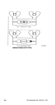

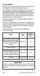
Table Of Contents
- General Information
- Installation
- Component Identification
- Maintenance
- Sequence of Operation
- Troubleshooting
- Safety Limits
- Control Board Testing
- Troubleshooting By Symptom
- Symptom #4
- Symptom #1 Ice Machine will not run
- Compressor Electrical Diagnostics
- Symptom #2 Low Production, Long Freeze
- Symptom #2 - Freeze Cycle Refrigeration System Operational Analysis Tables
- Freeze Cycle Refrigeration System Operational Analysis Table Procedures
- Before Beginning Service
- Ice Production Check
- Installation/Visual Inspection Checklist
- Water System Checklist
- Ice Formation Pattern
- Analyzing Discharge Pressure in the Freeze Cycle
- Analyzing Suction Pressure
- Single Expansion Valve Ice Machines Comparing Evaporator Inlet and Outlet Temperatures
- Multiple Expansion Valve Ice Machines Comparing Evaporator Inlet and Outlet Temperatures
- Harvest Valve Analysis
- Discharge Line Temperature Analysis
- Water Regulating Valve
- Final Analysis
- Harvest Problems
- Component Check Procedures
- Electrical Components
- Compressor Electrical Diagnostics
- Refrigeration Components
- Refrigerant Recovery/Evacuation
- System Contamination Clean-Up
- Specifications
- Charts
- Diagrams
- Wiring Diagrams
- Wiring Diagram Legend
- Wiring Diagrams Before Energy Efficient & EnergyStar Machines
- S320 Self Contained - 1 Phase
- S300/S420/S450/ S500 (after serial number 110074051) - Self Contained - 1 Phase
- S500 (before serial number 110074051) S600/S850/S1000/S1200- Self Contained- 1 Phase
- S850/S1000/S1200 - Self Contained - 3 Phase
- S500 Danfoss Compressor (after serial number 110074051) - Remote - 1 Phase
- S500 (before serial number 110074051)/ S600/S850/S1000/S1200 - Remote - 1 Phase
- S850/S1000/S1200 - Remote - 3 Phase
- S1400/S1600/S1800 - Self-Contained - 1 Phase
- S1400/S1600/S1800 - Self-Contained - 3 Phase
- S1400/S1600/S1800 - Remote - 1 Phase
- S1400/S1600/S1800 - Remote - 3 Phase
- Wiring Diagrams for Energy Efficient & EnergyStar Machines
- S300/S420/S450/S500 Self-Contained - 1 Phase
- S600/S850/S1000/S1200 Self-Contained - 1 Phase
- S850/S1000/S1200 Self-Contained - 3 Phase
- S1400/S1800 Self-Contained - 1 Phase
- S1400/S1800 Self-Contained - 3 Phase
- S3300 Water-Cooled - 3 phase
- S500 Remote - 1 Phase
- S600/S850/S1000/S1200 Remote - 1 Phase
- S850/S1000/S1200 Remote - 3 Phase
- S1400/S1800 Remote - 1 Phase
- S1400/S1800 Remote - 3 Phase
- Electronic Control Board
- Refrigeration Tubing Schematics
- Wiring Diagrams
Part Number 80-1479-3 7/10 183
REPLACING PRESSURE CONTROLS WITHOUT
REMOVING REFRIGERANT CHARGE
This procedure reduces repair time and cost. Use it
when any of the following components require
replacement, and the refrigeration system is
operational and leak-free.
• Fan cycle control (air cooled only)
• Water regulating valve (water cooled only)
• High pressure cut-out control
• High side service valve
• Low side service valve
1. Disconnect power to the ice machine.
2. Follow all manufacturer’s instructions supplied
with the pinch-off tool. Position the pinch-off tool
around the tubing as far from the pressure control
as feasible. (See the figure on next page.) Clamp
down on the tubing until the pinch-off is complete.
3. Cut the tubing of the defective component with a
small tubing cutter.
4. Solder the replacement component in place.
Allow the solder joint to cool.
5. Remove the pinch-off tool.
6. Re-round the tubing. Position the flattened tubing
in the proper hole in the pinch-off tool. Tighten the
wing nuts until the block is tight and the tubing is
rounded.
NOTE: The pressure controls will operate normally
once the tubing is re-rounded. Tubing may not re-
round 100%.
Important
This is a required in-warranty repair procedure.
!
Warning
Do not unsolder a defective component. Cut it out of
the system. Do not remove the pinch-off tool until the
new component is securely in place.