
Specifications

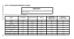
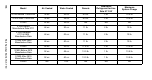
Table Of Contents
- General Information
- Installation
- Component Identification
- Maintenance
- Sequence of Operation
- Troubleshooting
- Safety Limits
- Control Board Testing
- Troubleshooting By Symptom
- Symptom #4
- Symptom #1 Ice Machine will not run
- Compressor Electrical Diagnostics
- Symptom #2 Low Production, Long Freeze
- Symptom #2 - Freeze Cycle Refrigeration System Operational Analysis Tables
- Freeze Cycle Refrigeration System Operational Analysis Table Procedures
- Before Beginning Service
- Ice Production Check
- Installation/Visual Inspection Checklist
- Water System Checklist
- Ice Formation Pattern
- Analyzing Discharge Pressure in the Freeze Cycle
- Analyzing Suction Pressure
- Single Expansion Valve Ice Machines Comparing Evaporator Inlet and Outlet Temperatures
- Multiple Expansion Valve Ice Machines Comparing Evaporator Inlet and Outlet Temperatures
- Harvest Valve Analysis
- Discharge Line Temperature Analysis
- Water Regulating Valve
- Final Analysis
- Harvest Problems
- Component Check Procedures
- Electrical Components
- Compressor Electrical Diagnostics
- Refrigeration Components
- Refrigerant Recovery/Evacuation
- System Contamination Clean-Up
- Specifications
- Charts
- Diagrams
- Wiring Diagrams
- Wiring Diagram Legend
- Wiring Diagrams Before Energy Efficient & EnergyStar Machines
- S320 Self Contained - 1 Phase
- S300/S420/S450/ S500 (after serial number 110074051) - Self Contained - 1 Phase
- S500 (before serial number 110074051) S600/S850/S1000/S1200- Self Contained- 1 Phase
- S850/S1000/S1200 - Self Contained - 3 Phase
- S500 Danfoss Compressor (after serial number 110074051) - Remote - 1 Phase
- S500 (before serial number 110074051)/ S600/S850/S1000/S1200 - Remote - 1 Phase
- S850/S1000/S1200 - Remote - 3 Phase
- S1400/S1600/S1800 - Self-Contained - 1 Phase
- S1400/S1600/S1800 - Self-Contained - 3 Phase
- S1400/S1600/S1800 - Remote - 1 Phase
- S1400/S1600/S1800 - Remote - 3 Phase
- Wiring Diagrams for Energy Efficient & EnergyStar Machines
- S300/S420/S450/S500 Self-Contained - 1 Phase
- S600/S850/S1000/S1200 Self-Contained - 1 Phase
- S850/S1000/S1200 Self-Contained - 3 Phase
- S1400/S1800 Self-Contained - 1 Phase
- S1400/S1800 Self-Contained - 3 Phase
- S3300 Water-Cooled - 3 phase
- S500 Remote - 1 Phase
- S600/S850/S1000/S1200 Remote - 1 Phase
- S850/S1000/S1200 Remote - 3 Phase
- S1400/S1800 Remote - 1 Phase
- S1400/S1800 Remote - 3 Phase
- Electronic Control Board
- Refrigeration Tubing Schematics
- Wiring Diagrams

182 Part Number 80-1479-3 7/10
10. Follow the normal evacuation procedure, except
replace the evacuation step with the following:
A. Pull vacuum to 1000 microns. Break the
vacuum with dry nitrogen and sweep the
system. Pressurize to a minimum of 5 psig
(35 kPa, .35 bar).
B. Change the vacuum pump oil.
C. Pull vacuum to 500 microns. Break the
vacuum with dry nitrogen and sweep the
system. Pressurize to a minimum of 5 psig
(35 kPa, .35 bar).
D. Change the vacuum pump oil.
E. Pull vacuum to 500 microns. Run the vacuum
pump for 1/2 hour on self-contained models,
1 hour on remotes.
NOTE: You may perform a standing vacuum test to
make a preliminary leak check. You should use an
electronic leak detector after system charging to be
sure there are no leaks.
11. Charge the system with the proper refrigerant to
the nameplate charge.
12. Operate the ice machine for one hour. Then,
check the pressure drop across the suction line
filter-drier.
A. If the pressure drop is less than 1 psig
(7 kPa, .7 bar), the filter-drier should be
adequate for complete cleanup.
B. If the pressure drop exceeds 1 psig (7 kPa, .7
bar), change the suction line filter-drier and
the liquid line drier. Repeat until the pressure
drop is acceptable.
13. Operate the ice machine for 48-72 hours. Then
remove the suction line drier and change the
liquid line drier.
14. Follow normal evacuation procedures.
Important
Dry n itrogen i s re commended fo r this p rocedure.
This will prevent CFC release.