
Specifications
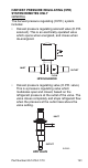


Table Of Contents
- General Information
- Installation
- Component Identification
- Maintenance
- Sequence of Operation
- Troubleshooting
- Safety Limits
- Control Board Testing
- Troubleshooting By Symptom
- Symptom #4
- Symptom #1 Ice Machine will not run
- Compressor Electrical Diagnostics
- Symptom #2 Low Production, Long Freeze
- Symptom #2 - Freeze Cycle Refrigeration System Operational Analysis Tables
- Freeze Cycle Refrigeration System Operational Analysis Table Procedures
- Before Beginning Service
- Ice Production Check
- Installation/Visual Inspection Checklist
- Water System Checklist
- Ice Formation Pattern
- Analyzing Discharge Pressure in the Freeze Cycle
- Analyzing Suction Pressure
- Single Expansion Valve Ice Machines Comparing Evaporator Inlet and Outlet Temperatures
- Multiple Expansion Valve Ice Machines Comparing Evaporator Inlet and Outlet Temperatures
- Harvest Valve Analysis
- Discharge Line Temperature Analysis
- Water Regulating Valve
- Final Analysis
- Harvest Problems
- Component Check Procedures
- Electrical Components
- Compressor Electrical Diagnostics
- Refrigeration Components
- Refrigerant Recovery/Evacuation
- System Contamination Clean-Up
- Specifications
- Charts
- Diagrams
- Wiring Diagrams
- Wiring Diagram Legend
- Wiring Diagrams Before Energy Efficient & EnergyStar Machines
- S320 Self Contained - 1 Phase
- S300/S420/S450/ S500 (after serial number 110074051) - Self Contained - 1 Phase
- S500 (before serial number 110074051) S600/S850/S1000/S1200- Self Contained- 1 Phase
- S850/S1000/S1200 - Self Contained - 3 Phase
- S500 Danfoss Compressor (after serial number 110074051) - Remote - 1 Phase
- S500 (before serial number 110074051)/ S600/S850/S1000/S1200 - Remote - 1 Phase
- S850/S1000/S1200 - Remote - 3 Phase
- S1400/S1600/S1800 - Self-Contained - 1 Phase
- S1400/S1600/S1800 - Self-Contained - 3 Phase
- S1400/S1600/S1800 - Remote - 1 Phase
- S1400/S1600/S1800 - Remote - 3 Phase
- Wiring Diagrams for Energy Efficient & EnergyStar Machines
- S300/S420/S450/S500 Self-Contained - 1 Phase
- S600/S850/S1000/S1200 Self-Contained - 1 Phase
- S850/S1000/S1200 Self-Contained - 3 Phase
- S1400/S1800 Self-Contained - 1 Phase
- S1400/S1800 Self-Contained - 3 Phase
- S3300 Water-Cooled - 3 phase
- S500 Remote - 1 Phase
- S600/S850/S1000/S1200 Remote - 1 Phase
- S850/S1000/S1200 Remote - 3 Phase
- S1400/S1800 Remote - 1 Phase
- S1400/S1800 Remote - 3 Phase
- Electronic Control Board
- Refrigeration Tubing Schematics
- Wiring Diagrams

164 Part Number 80-1479-3 7/10
HEAD PRESSURE CONTROL VALVE
Manitowoc remote systems require head pressure
control valves with special settings. Replace defective
head pressure control valves only with “original”
Manitowoc replacement parts.
OPERATION
The R404A head pressure control valve is non
adjustable.
At ambient temperatures of approximately 70°F (21°C)
or above, refrigerant flows through the valve from the
condenser to the receiver inlet. At temperatures below
this (or at higher temperatures if it is raining), the head
pressure control dome’s nitrogen charge closes the
condenser port and opens the bypass port from the
compressor discharge line.
In this modulating mode, the valve maintains minimum
head pressure by building up liquid in the condenser
and bypassing discharge gas directly to the receiver.
DIAGNOSING
1. Determine if the coil is clean. Air passes through
the condenser from the bottom up. Verify the coil
is clean by looking from the bottom up. Do not
look down through the fan.
2. Determine the air temperature entering the
remote condenser.
3. Determine if the head pressure is high or low in
relationship to the outside temperature. (Refer to
the proper “Cycle Times/24-Hour Ice Production/
Refrigerant Pressure Charts” page 191).
4. Determine the temperature of the liquid line
entering the receiver by feeling it. This line is
normally warm; “body temperature.”