
Specifications
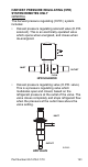

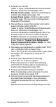
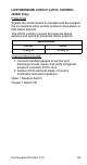
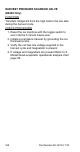

Table Of Contents
- General Information
- Installation
- Component Identification
- Maintenance
- Sequence of Operation
- Troubleshooting
- Safety Limits
- Control Board Testing
- Troubleshooting By Symptom
- Symptom #4
- Symptom #1 Ice Machine will not run
- Compressor Electrical Diagnostics
- Symptom #2 Low Production, Long Freeze
- Symptom #2 - Freeze Cycle Refrigeration System Operational Analysis Tables
- Freeze Cycle Refrigeration System Operational Analysis Table Procedures
- Before Beginning Service
- Ice Production Check
- Installation/Visual Inspection Checklist
- Water System Checklist
- Ice Formation Pattern
- Analyzing Discharge Pressure in the Freeze Cycle
- Analyzing Suction Pressure
- Single Expansion Valve Ice Machines Comparing Evaporator Inlet and Outlet Temperatures
- Multiple Expansion Valve Ice Machines Comparing Evaporator Inlet and Outlet Temperatures
- Harvest Valve Analysis
- Discharge Line Temperature Analysis
- Water Regulating Valve
- Final Analysis
- Harvest Problems
- Component Check Procedures
- Electrical Components
- Compressor Electrical Diagnostics
- Refrigeration Components
- Refrigerant Recovery/Evacuation
- System Contamination Clean-Up
- Specifications
- Charts
- Diagrams
- Wiring Diagrams
- Wiring Diagram Legend
- Wiring Diagrams Before Energy Efficient & EnergyStar Machines
- S320 Self Contained - 1 Phase
- S300/S420/S450/ S500 (after serial number 110074051) - Self Contained - 1 Phase
- S500 (before serial number 110074051) S600/S850/S1000/S1200- Self Contained- 1 Phase
- S850/S1000/S1200 - Self Contained - 3 Phase
- S500 Danfoss Compressor (after serial number 110074051) - Remote - 1 Phase
- S500 (before serial number 110074051)/ S600/S850/S1000/S1200 - Remote - 1 Phase
- S850/S1000/S1200 - Remote - 3 Phase
- S1400/S1600/S1800 - Self-Contained - 1 Phase
- S1400/S1600/S1800 - Self-Contained - 3 Phase
- S1400/S1600/S1800 - Remote - 1 Phase
- S1400/S1600/S1800 - Remote - 3 Phase
- Wiring Diagrams for Energy Efficient & EnergyStar Machines
- S300/S420/S450/S500 Self-Contained - 1 Phase
- S600/S850/S1000/S1200 Self-Contained - 1 Phase
- S850/S1000/S1200 Self-Contained - 3 Phase
- S1400/S1800 Self-Contained - 1 Phase
- S1400/S1800 Self-Contained - 3 Phase
- S3300 Water-Cooled - 3 phase
- S500 Remote - 1 Phase
- S600/S850/S1000/S1200 Remote - 1 Phase
- S850/S1000/S1200 Remote - 3 Phase
- S1400/S1800 Remote - 1 Phase
- S1400/S1800 Remote - 3 Phase
- Electronic Control Board
- Refrigeration Tubing Schematics
- Wiring Diagrams

162 Part Number 80-1479-3 7/10
FREEZE CYCLE
The H.P.R. system is not used during the freeze cycle.
The H.P.R. solenoid is closed (de-energized),
preventing refrigerant flow into the H.P.R. valve.
HARVEST CYCLE
During the harvest cycle, the check valve in the
discharge line prevents refrigerant in the remote
condenser and receiver from backfeeding into the
evaporator and condensing to liquid.
The H.P.R. solenoid is opened (energized) during the
harvest cycle, allowing refrigerant gas from the top of
the receiver to flow into the H.P.R. valve. The H.P.R.
valve modulates open and closed, raising the suction
pressure high enough to sustain heat for the harvest
cycle, without allowing refrigerant to condense to liquid
in the evaporator.
In general, harvest cycle suction pressure rises, then
stabilizes in the range of 70-100 psig (517-758 kPA).
Exact pressures vary from model to model. Refer to
the “Operational Refrigerant Pressures” charts
page 191.
HPR DIAGNOSTICS
Steps 1 through 4 can be quickly verified without
attaching a manifold gauge set or thermometer.
All questions must have a yes answer to continue
the diagnostic procedure.
1. Liquid line warm?
(Body temperature is normal)
If liquid line is cooler than body temperature, refer
to head pressure control valve diagnostics
page 164.
2. Ice fill pattern normal?
Refer to “Ice Formation Pattern” if ice fill is not
normal page 110.