
Specifications
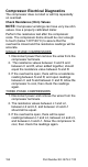
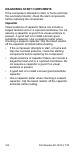


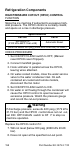
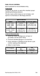

Table Of Contents
- General Information
- Installation
- Component Identification
- Maintenance
- Sequence of Operation
- Troubleshooting
- Safety Limits
- Control Board Testing
- Troubleshooting By Symptom
- Symptom #4
- Symptom #1 Ice Machine will not run
- Compressor Electrical Diagnostics
- Symptom #2 Low Production, Long Freeze
- Symptom #2 - Freeze Cycle Refrigeration System Operational Analysis Tables
- Freeze Cycle Refrigeration System Operational Analysis Table Procedures
- Before Beginning Service
- Ice Production Check
- Installation/Visual Inspection Checklist
- Water System Checklist
- Ice Formation Pattern
- Analyzing Discharge Pressure in the Freeze Cycle
- Analyzing Suction Pressure
- Single Expansion Valve Ice Machines Comparing Evaporator Inlet and Outlet Temperatures
- Multiple Expansion Valve Ice Machines Comparing Evaporator Inlet and Outlet Temperatures
- Harvest Valve Analysis
- Discharge Line Temperature Analysis
- Water Regulating Valve
- Final Analysis
- Harvest Problems
- Component Check Procedures
- Electrical Components
- Compressor Electrical Diagnostics
- Refrigeration Components
- Refrigerant Recovery/Evacuation
- System Contamination Clean-Up
- Specifications
- Charts
- Diagrams
- Wiring Diagrams
- Wiring Diagram Legend
- Wiring Diagrams Before Energy Efficient & EnergyStar Machines
- S320 Self Contained - 1 Phase
- S300/S420/S450/ S500 (after serial number 110074051) - Self Contained - 1 Phase
- S500 (before serial number 110074051) S600/S850/S1000/S1200- Self Contained- 1 Phase
- S850/S1000/S1200 - Self Contained - 3 Phase
- S500 Danfoss Compressor (after serial number 110074051) - Remote - 1 Phase
- S500 (before serial number 110074051)/ S600/S850/S1000/S1200 - Remote - 1 Phase
- S850/S1000/S1200 - Remote - 3 Phase
- S1400/S1600/S1800 - Self-Contained - 1 Phase
- S1400/S1600/S1800 - Self-Contained - 3 Phase
- S1400/S1600/S1800 - Remote - 1 Phase
- S1400/S1600/S1800 - Remote - 3 Phase
- Wiring Diagrams for Energy Efficient & EnergyStar Machines
- S300/S420/S450/S500 Self-Contained - 1 Phase
- S600/S850/S1000/S1200 Self-Contained - 1 Phase
- S850/S1000/S1200 Self-Contained - 3 Phase
- S1400/S1800 Self-Contained - 1 Phase
- S1400/S1800 Self-Contained - 3 Phase
- S3300 Water-Cooled - 3 phase
- S500 Remote - 1 Phase
- S600/S850/S1000/S1200 Remote - 1 Phase
- S850/S1000/S1200 Remote - 3 Phase
- S1400/S1800 Remote - 1 Phase
- S1400/S1800 Remote - 3 Phase
- Electronic Control Board
- Refrigeration Tubing Schematics
- Wiring Diagrams
158 Part Number 80-1479-3 7/10
Refrigeration Components
HIGH PRESSURE CUTOUT (HPCO) CONTROL
FUNCTION
Stops the ice machine if subjected to excessive high-
side pressure. The HPCO control is normally closed,
and opens on a rise in discharge pressure.
CHECK PROCEDURE
1. Set ICE/OFF/CLEAN switch to OFF, (Manual
reset HPCO reset if tripped).
2. Connect manifold gauges.
3. Hook voltmeter in parallel across the HPCO,
leaving wires attached.
4. On water-cooled models, close the water service
valve to the water condenser inlet. On self-
contained air-cooled and remote models,
disconnect the fan motor.
5. Set ICE/OFF/CLEAN switch to ICE.
6. No water or air flowing through the condenser will
cause the HPCO control to open because of
excessive pressure. Watch the pressure gauge
and record the cut-out pressure.
Replace the HPCO control if it:
7. Will not reset [below 300 psig (2068 kPa 20.68
bar).
8. Does not open at the specified cut-out point.
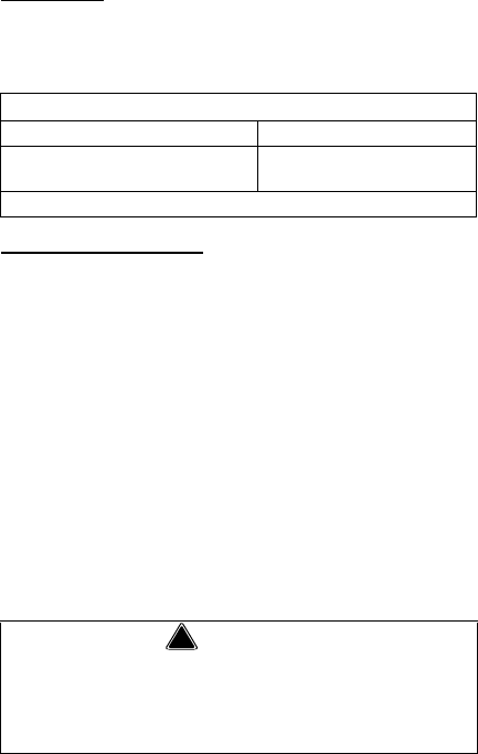
Specifications
Cut-Out Cut-In
450 psig ±10
(3103 kPa ±69 31 bar ±.69)
Automatic Reset
(Must be below 300 psig (2068 kPa 20.68 bar) to reset.)
!
Warning
If di scharge pressure excee ds 4 60 psig (3172 kPa
31.72 ba r) and the HPCO control does not cut out,
set ICE/ OFF/CLEAN switch to OF F to stop ice
machine operation.