
Specifications
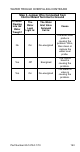
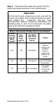
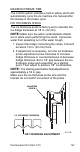
Table Of Contents
- General Information
- Installation
- Component Identification
- Maintenance
- Sequence of Operation
- Troubleshooting
- Safety Limits
- Control Board Testing
- Troubleshooting By Symptom
- Symptom #4
- Symptom #1 Ice Machine will not run
- Compressor Electrical Diagnostics
- Symptom #2 Low Production, Long Freeze
- Symptom #2 - Freeze Cycle Refrigeration System Operational Analysis Tables
- Freeze Cycle Refrigeration System Operational Analysis Table Procedures
- Before Beginning Service
- Ice Production Check
- Installation/Visual Inspection Checklist
- Water System Checklist
- Ice Formation Pattern
- Analyzing Discharge Pressure in the Freeze Cycle
- Analyzing Suction Pressure
- Single Expansion Valve Ice Machines Comparing Evaporator Inlet and Outlet Temperatures
- Multiple Expansion Valve Ice Machines Comparing Evaporator Inlet and Outlet Temperatures
- Harvest Valve Analysis
- Discharge Line Temperature Analysis
- Water Regulating Valve
- Final Analysis
- Harvest Problems
- Component Check Procedures
- Electrical Components
- Compressor Electrical Diagnostics
- Refrigeration Components
- Refrigerant Recovery/Evacuation
- System Contamination Clean-Up
- Specifications
- Charts
- Diagrams
- Wiring Diagrams
- Wiring Diagram Legend
- Wiring Diagrams Before Energy Efficient & EnergyStar Machines
- S320 Self Contained - 1 Phase
- S300/S420/S450/ S500 (after serial number 110074051) - Self Contained - 1 Phase
- S500 (before serial number 110074051) S600/S850/S1000/S1200- Self Contained- 1 Phase
- S850/S1000/S1200 - Self Contained - 3 Phase
- S500 Danfoss Compressor (after serial number 110074051) - Remote - 1 Phase
- S500 (before serial number 110074051)/ S600/S850/S1000/S1200 - Remote - 1 Phase
- S850/S1000/S1200 - Remote - 3 Phase
- S1400/S1600/S1800 - Self-Contained - 1 Phase
- S1400/S1600/S1800 - Self-Contained - 3 Phase
- S1400/S1600/S1800 - Remote - 1 Phase
- S1400/S1600/S1800 - Remote - 3 Phase
- Wiring Diagrams for Energy Efficient & EnergyStar Machines
- S300/S420/S450/S500 Self-Contained - 1 Phase
- S600/S850/S1000/S1200 Self-Contained - 1 Phase
- S850/S1000/S1200 Self-Contained - 3 Phase
- S1400/S1800 Self-Contained - 1 Phase
- S1400/S1800 Self-Contained - 3 Phase
- S3300 Water-Cooled - 3 phase
- S500 Remote - 1 Phase
- S600/S850/S1000/S1200 Remote - 1 Phase
- S850/S1000/S1200 Remote - 3 Phase
- S1400/S1800 Remote - 1 Phase
- S1400/S1800 Remote - 3 Phase
- Electronic Control Board
- Refrigeration Tubing Schematics
- Wiring Diagrams
150 Part Number 80-1479-3 7/10
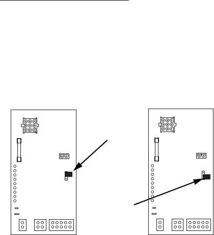
HARVEST CYCLE CIRCUITRY
The water level probe does not control the water inlet
valve during the harvest cycle. During the harvest
cycle water purge, the water inlet valve energizes and
de-energizes strictly by time. The harvest water purge
may be set at 45 seconds (top and center terminals) or
0 seconds (center and bottom terminals). Set the
harvest water purge to 0 seconds when reverse
osmosis or deionized water is used. Use the factory
setting of 45 seconds for all other types of water.
0 Second
Jumper
Position
45 Second
Jumper
Position