
Specifications
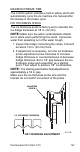
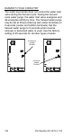
Table Of Contents
- General Information
- Installation
- Component Identification
- Maintenance
- Sequence of Operation
- Troubleshooting
- Safety Limits
- Control Board Testing
- Troubleshooting By Symptom
- Symptom #4
- Symptom #1 Ice Machine will not run
- Compressor Electrical Diagnostics
- Symptom #2 Low Production, Long Freeze
- Symptom #2 - Freeze Cycle Refrigeration System Operational Analysis Tables
- Freeze Cycle Refrigeration System Operational Analysis Table Procedures
- Before Beginning Service
- Ice Production Check
- Installation/Visual Inspection Checklist
- Water System Checklist
- Ice Formation Pattern
- Analyzing Discharge Pressure in the Freeze Cycle
- Analyzing Suction Pressure
- Single Expansion Valve Ice Machines Comparing Evaporator Inlet and Outlet Temperatures
- Multiple Expansion Valve Ice Machines Comparing Evaporator Inlet and Outlet Temperatures
- Harvest Valve Analysis
- Discharge Line Temperature Analysis
- Water Regulating Valve
- Final Analysis
- Harvest Problems
- Component Check Procedures
- Electrical Components
- Compressor Electrical Diagnostics
- Refrigeration Components
- Refrigerant Recovery/Evacuation
- System Contamination Clean-Up
- Specifications
- Charts
- Diagrams
- Wiring Diagrams
- Wiring Diagram Legend
- Wiring Diagrams Before Energy Efficient & EnergyStar Machines
- S320 Self Contained - 1 Phase
- S300/S420/S450/ S500 (after serial number 110074051) - Self Contained - 1 Phase
- S500 (before serial number 110074051) S600/S850/S1000/S1200- Self Contained- 1 Phase
- S850/S1000/S1200 - Self Contained - 3 Phase
- S500 Danfoss Compressor (after serial number 110074051) - Remote - 1 Phase
- S500 (before serial number 110074051)/ S600/S850/S1000/S1200 - Remote - 1 Phase
- S850/S1000/S1200 - Remote - 3 Phase
- S1400/S1600/S1800 - Self-Contained - 1 Phase
- S1400/S1600/S1800 - Self-Contained - 3 Phase
- S1400/S1600/S1800 - Remote - 1 Phase
- S1400/S1600/S1800 - Remote - 3 Phase
- Wiring Diagrams for Energy Efficient & EnergyStar Machines
- S300/S420/S450/S500 Self-Contained - 1 Phase
- S600/S850/S1000/S1200 Self-Contained - 1 Phase
- S850/S1000/S1200 Self-Contained - 3 Phase
- S1400/S1800 Self-Contained - 1 Phase
- S1400/S1800 Self-Contained - 3 Phase
- S3300 Water-Cooled - 3 phase
- S500 Remote - 1 Phase
- S600/S850/S1000/S1200 Remote - 1 Phase
- S850/S1000/S1200 Remote - 3 Phase
- S1400/S1800 Remote - 1 Phase
- S1400/S1800 Remote - 3 Phase
- Electronic Control Board
- Refrigeration Tubing Schematics
- Wiring Diagrams

Part Number 80-1479-3 7/10 141
WATER LEVEL CONTROL CIRCUITRY
The water level probe circuit can be monitored by
watching the water level light. The water level light is
on when water contacts the probe, and off when no
water is in contact with the probe. The water level light
functions any time power is applied to the ice machine,
regardless of toggle switch position.
FREEZE CYCLE WATER LEVEL SETTING
During the Freeze cycle, the water level probe is set to
maintain the proper water level above the water pump
housing. The water level is not adjustable. If the water
level is incorrect, check the water level probe position.
Reposition or replace the probe as necessary.
WATER INLET VALVE SAFETY SHUT-OFF
In the event of a water level probe failure, this feature
limits the water inlet valve to a six-minute on time.
Regardless of the water level probe input, the control
board automatically shuts off the water inlet valve if it
remains on for 12 continuous minutes. This is
important to remember when performing diagnostic
procedures on the water level control circuitry.
FREEZE CYCLE CIRCUITRY
Manitowoc’s electronic sensing circuit does not rely on
float switches or timers to maintain consistent water
level control. During the Freeze cycle, the water inlet
valve energizes and de-energizes in conjunction with
the water level probe located in the water trough.
During the first 45 seconds of the Freeze cycle:
• The water inlet valve is ON when there is no water
in contact with the water level probe.
• The water inlet valve turns OFF after water
contacts the water level probe for 3 continuous
seconds.
• The water inlet valve will cycle ON and OFF as
many times as needed to fill the water trough.
After 45 seconds into the Freeze cycle:
The water inlet valve will cycle ON, and then OFF one
more time to refill the water trough. The water inlet
valve is now OFF for the duration of the freeze cycle.
4.