
Specifications
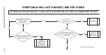
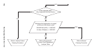

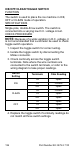

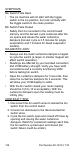
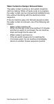

Table Of Contents
- General Information
- Installation
- Component Identification
- Maintenance
- Sequence of Operation
- Troubleshooting
- Safety Limits
- Control Board Testing
- Troubleshooting By Symptom
- Symptom #4
- Symptom #1 Ice Machine will not run
- Compressor Electrical Diagnostics
- Symptom #2 Low Production, Long Freeze
- Symptom #2 - Freeze Cycle Refrigeration System Operational Analysis Tables
- Freeze Cycle Refrigeration System Operational Analysis Table Procedures
- Before Beginning Service
- Ice Production Check
- Installation/Visual Inspection Checklist
- Water System Checklist
- Ice Formation Pattern
- Analyzing Discharge Pressure in the Freeze Cycle
- Analyzing Suction Pressure
- Single Expansion Valve Ice Machines Comparing Evaporator Inlet and Outlet Temperatures
- Multiple Expansion Valve Ice Machines Comparing Evaporator Inlet and Outlet Temperatures
- Harvest Valve Analysis
- Discharge Line Temperature Analysis
- Water Regulating Valve
- Final Analysis
- Harvest Problems
- Component Check Procedures
- Electrical Components
- Compressor Electrical Diagnostics
- Refrigeration Components
- Refrigerant Recovery/Evacuation
- System Contamination Clean-Up
- Specifications
- Charts
- Diagrams
- Wiring Diagrams
- Wiring Diagram Legend
- Wiring Diagrams Before Energy Efficient & EnergyStar Machines
- S320 Self Contained - 1 Phase
- S300/S420/S450/ S500 (after serial number 110074051) - Self Contained - 1 Phase
- S500 (before serial number 110074051) S600/S850/S1000/S1200- Self Contained- 1 Phase
- S850/S1000/S1200 - Self Contained - 3 Phase
- S500 Danfoss Compressor (after serial number 110074051) - Remote - 1 Phase
- S500 (before serial number 110074051)/ S600/S850/S1000/S1200 - Remote - 1 Phase
- S850/S1000/S1200 - Remote - 3 Phase
- S1400/S1600/S1800 - Self-Contained - 1 Phase
- S1400/S1600/S1800 - Self-Contained - 3 Phase
- S1400/S1600/S1800 - Remote - 1 Phase
- S1400/S1600/S1800 - Remote - 3 Phase
- Wiring Diagrams for Energy Efficient & EnergyStar Machines
- S300/S420/S450/S500 Self-Contained - 1 Phase
- S600/S850/S1000/S1200 Self-Contained - 1 Phase
- S850/S1000/S1200 Self-Contained - 3 Phase
- S1400/S1800 Self-Contained - 1 Phase
- S1400/S1800 Self-Contained - 3 Phase
- S3300 Water-Cooled - 3 phase
- S500 Remote - 1 Phase
- S600/S850/S1000/S1200 Remote - 1 Phase
- S850/S1000/S1200 Remote - 3 Phase
- S1400/S1800 Remote - 1 Phase
- S1400/S1800 Remote - 3 Phase
- Electronic Control Board
- Refrigeration Tubing Schematics
- Wiring Diagrams

Part Number 80-1479-3 7/10 137
BIN SWITCH
FUNCTION
Movement of the water curtain/ice dampers control bin
switch operation. The bin switch has two main
functions:
1. Terminating the Harvest cycle and returning the
ice machine to the Freeze cycle. This occurs
when the bin switch is opened and closed again
within 30 seconds during the Harvest cycle.
2. Automatic ice machine shut-off.
If the storage bin is full at the end of a Harvest
cycle, the sheet of cubes fails to clear the water
curtain/ice dampers and holds it open. After the
water curtain/ice dampers are held open for 30
seconds, the ice machine shuts off. The ice
machine remains off until enough ice is removed
from the storage bin to allow the sheet of cubes to
drop clear of the water curtain/ice dampers. As
the water curtain/ice dampers swing back to the
operating position, the bin switch closes and the
ice machine restarts, provide the 3-minute delay
has expired.
SPECIFICATIONS
The bin switch is a magnetically operated reed switch.
The magnet is attached to the lower right corner of the
water curtain/ice dampers. The switch is attached to
the right bulkhead wall.
The bin switch is connected to a varying D.C. voltage
circuit. (Voltage does not remain constant.)
NOTE: Because of a wide variation in D.C. voltage, it
is not recommended that a voltmeter be used to check
bin switch operation.
Important
The water cu rtain/ice dampers m ust b e ON ( bin
switch closed) to start ice making.