
Specifications
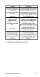

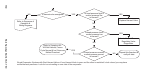
Table Of Contents
- General Information
- Installation
- Component Identification
- Maintenance
- Sequence of Operation
- Troubleshooting
- Safety Limits
- Control Board Testing
- Troubleshooting By Symptom
- Symptom #4
- Symptom #1 Ice Machine will not run
- Compressor Electrical Diagnostics
- Symptom #2 Low Production, Long Freeze
- Symptom #2 - Freeze Cycle Refrigeration System Operational Analysis Tables
- Freeze Cycle Refrigeration System Operational Analysis Table Procedures
- Before Beginning Service
- Ice Production Check
- Installation/Visual Inspection Checklist
- Water System Checklist
- Ice Formation Pattern
- Analyzing Discharge Pressure in the Freeze Cycle
- Analyzing Suction Pressure
- Single Expansion Valve Ice Machines Comparing Evaporator Inlet and Outlet Temperatures
- Multiple Expansion Valve Ice Machines Comparing Evaporator Inlet and Outlet Temperatures
- Harvest Valve Analysis
- Discharge Line Temperature Analysis
- Water Regulating Valve
- Final Analysis
- Harvest Problems
- Component Check Procedures
- Electrical Components
- Compressor Electrical Diagnostics
- Refrigeration Components
- Refrigerant Recovery/Evacuation
- System Contamination Clean-Up
- Specifications
- Charts
- Diagrams
- Wiring Diagrams
- Wiring Diagram Legend
- Wiring Diagrams Before Energy Efficient & EnergyStar Machines
- S320 Self Contained - 1 Phase
- S300/S420/S450/ S500 (after serial number 110074051) - Self Contained - 1 Phase
- S500 (before serial number 110074051) S600/S850/S1000/S1200- Self Contained- 1 Phase
- S850/S1000/S1200 - Self Contained - 3 Phase
- S500 Danfoss Compressor (after serial number 110074051) - Remote - 1 Phase
- S500 (before serial number 110074051)/ S600/S850/S1000/S1200 - Remote - 1 Phase
- S850/S1000/S1200 - Remote - 3 Phase
- S1400/S1600/S1800 - Self-Contained - 1 Phase
- S1400/S1600/S1800 - Self-Contained - 3 Phase
- S1400/S1600/S1800 - Remote - 1 Phase
- S1400/S1600/S1800 - Remote - 3 Phase
- Wiring Diagrams for Energy Efficient & EnergyStar Machines
- S300/S420/S450/S500 Self-Contained - 1 Phase
- S600/S850/S1000/S1200 Self-Contained - 1 Phase
- S850/S1000/S1200 Self-Contained - 3 Phase
- S1400/S1800 Self-Contained - 1 Phase
- S1400/S1800 Self-Contained - 3 Phase
- S3300 Water-Cooled - 3 phase
- S500 Remote - 1 Phase
- S600/S850/S1000/S1200 Remote - 1 Phase
- S850/S1000/S1200 Remote - 3 Phase
- S1400/S1800 Remote - 1 Phase
- S1400/S1800 Remote - 3 Phase
- Electronic Control Board
- Refrigeration Tubing Schematics
- Wiring Diagrams

122 Part Number 80-1479-3 7/10
Discharge Line Temperature Analysis
GENERAL
Knowing if the discharge line temperature is
increasing, decreasing or remaining constant can be
an important diagnostic tool. Compressor discharge
line temperature on a normally operating ice machine
steadily increases throughout the freeze cycle.
Ambient air temperatures affect the discharge line
temperature.
Higher ambient air temperatures at the condenser
and/or higher inlet water temperature = higher
discharge line temperatures at the compressor.
Lower ambient air temperatures at the condenser and/
or lower supply water temperature= lower discharge
line temperatures at the compressor.
Regardless of ambient and water temperatures, the
freeze cycle discharge line temperature will be higher
than 150°F (66°C) [S850/S1000 Air & Water Machines
Only - 140°F (60°C)] at the end of the freeze cycle.
PROCEDURE
Connect a temperature probe on the compressor
discharge line with-in 6" of the compressor and
insulate.
Observe the discharge line temperature for the last
three minutes of the freeze cycle and record on the
table.
Discharge Line Temperature Above 150°F (66°C)
[S850/S1000 Air & Water Machines Only - 140°F
(60°C)] At End Of Freeze Cycle:
Ice machines that are operating normally will have
consistent minimum discharge line temperature of
150°F (66°C) [S850/S1000 Air & Water Machines Only
- 140°F (60°C)].