
Specifications
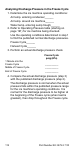
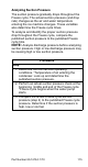
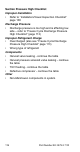
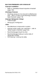


Table Of Contents
- General Information
- Installation
- Component Identification
- Maintenance
- Sequence of Operation
- Troubleshooting
- Safety Limits
- Control Board Testing
- Troubleshooting By Symptom
- Symptom #4
- Symptom #1 Ice Machine will not run
- Compressor Electrical Diagnostics
- Symptom #2 Low Production, Long Freeze
- Symptom #2 - Freeze Cycle Refrigeration System Operational Analysis Tables
- Freeze Cycle Refrigeration System Operational Analysis Table Procedures
- Before Beginning Service
- Ice Production Check
- Installation/Visual Inspection Checklist
- Water System Checklist
- Ice Formation Pattern
- Analyzing Discharge Pressure in the Freeze Cycle
- Analyzing Suction Pressure
- Single Expansion Valve Ice Machines Comparing Evaporator Inlet and Outlet Temperatures
- Multiple Expansion Valve Ice Machines Comparing Evaporator Inlet and Outlet Temperatures
- Harvest Valve Analysis
- Discharge Line Temperature Analysis
- Water Regulating Valve
- Final Analysis
- Harvest Problems
- Component Check Procedures
- Electrical Components
- Compressor Electrical Diagnostics
- Refrigeration Components
- Refrigerant Recovery/Evacuation
- System Contamination Clean-Up
- Specifications
- Charts
- Diagrams
- Wiring Diagrams
- Wiring Diagram Legend
- Wiring Diagrams Before Energy Efficient & EnergyStar Machines
- S320 Self Contained - 1 Phase
- S300/S420/S450/ S500 (after serial number 110074051) - Self Contained - 1 Phase
- S500 (before serial number 110074051) S600/S850/S1000/S1200- Self Contained- 1 Phase
- S850/S1000/S1200 - Self Contained - 3 Phase
- S500 Danfoss Compressor (after serial number 110074051) - Remote - 1 Phase
- S500 (before serial number 110074051)/ S600/S850/S1000/S1200 - Remote - 1 Phase
- S850/S1000/S1200 - Remote - 3 Phase
- S1400/S1600/S1800 - Self-Contained - 1 Phase
- S1400/S1600/S1800 - Self-Contained - 3 Phase
- S1400/S1600/S1800 - Remote - 1 Phase
- S1400/S1600/S1800 - Remote - 3 Phase
- Wiring Diagrams for Energy Efficient & EnergyStar Machines
- S300/S420/S450/S500 Self-Contained - 1 Phase
- S600/S850/S1000/S1200 Self-Contained - 1 Phase
- S850/S1000/S1200 Self-Contained - 3 Phase
- S1400/S1800 Self-Contained - 1 Phase
- S1400/S1800 Self-Contained - 3 Phase
- S3300 Water-Cooled - 3 phase
- S500 Remote - 1 Phase
- S600/S850/S1000/S1200 Remote - 1 Phase
- S850/S1000/S1200 Remote - 3 Phase
- S1400/S1800 Remote - 1 Phase
- S1400/S1800 Remote - 3 Phase
- Electronic Control Board
- Refrigeration Tubing Schematics
- Wiring Diagrams

118 Part Number 80-1479-3 7/10
Single Expansion Valve Ice Machines Comparing
Evaporator Inlet and Outlet Temperatures
NOTE: This procedure will not work on dual or Quad
expansion valve ice machines.
The temperatures of the suction lines entering and
leaving the evaporator alone cannot diagnose an ice
machine. However, comparing these temperatures
during the freeze cycle, along with using Manitowoc’s
Freeze Cycle Refrigeration System Operational
Analysis Table, can help diagnose an ice machine
malfunction.
The actual temperatures entering and leaving the
evaporator vary by model, and change throughout the
freeze cycle. This makes documenting the “normal”
inlet and outlet temperature readings difficult. The key
to the diagnosis lies in the difference between the two
temperatures five minutes into the freeze cycle. These
temperatures should be within 7° of each other.
Use this procedure to document freeze cycle inlet and
outlet temperatures.
1. Use a quality temperature meter, capable of
taking temperature readings on curved copper
lines.
2. Attach the temperature meter sensing device to
the copper lines entering and leaving the
evaporator.
3. Wait five minutes into the freeze cycle.
4. Record the evaporator inlet and outlet
temperatures after 5 minutes into the freeze cycle.
Determine the difference.
5. Record the information on the table.
Important
Do not simply insert the sensing device under the
insulation. It must be attached to and reading the
actual temperature of the copper line.