
Specifications
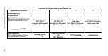
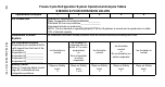
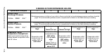
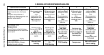
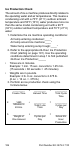
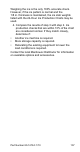
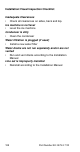
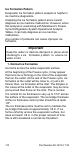
Table Of Contents
- General Information
- Installation
- Component Identification
- Maintenance
- Sequence of Operation
- Troubleshooting
- Safety Limits
- Control Board Testing
- Troubleshooting By Symptom
- Symptom #4
- Symptom #1 Ice Machine will not run
- Compressor Electrical Diagnostics
- Symptom #2 Low Production, Long Freeze
- Symptom #2 - Freeze Cycle Refrigeration System Operational Analysis Tables
- Freeze Cycle Refrigeration System Operational Analysis Table Procedures
- Before Beginning Service
- Ice Production Check
- Installation/Visual Inspection Checklist
- Water System Checklist
- Ice Formation Pattern
- Analyzing Discharge Pressure in the Freeze Cycle
- Analyzing Suction Pressure
- Single Expansion Valve Ice Machines Comparing Evaporator Inlet and Outlet Temperatures
- Multiple Expansion Valve Ice Machines Comparing Evaporator Inlet and Outlet Temperatures
- Harvest Valve Analysis
- Discharge Line Temperature Analysis
- Water Regulating Valve
- Final Analysis
- Harvest Problems
- Component Check Procedures
- Electrical Components
- Compressor Electrical Diagnostics
- Refrigeration Components
- Refrigerant Recovery/Evacuation
- System Contamination Clean-Up
- Specifications
- Charts
- Diagrams
- Wiring Diagrams
- Wiring Diagram Legend
- Wiring Diagrams Before Energy Efficient & EnergyStar Machines
- S320 Self Contained - 1 Phase
- S300/S420/S450/ S500 (after serial number 110074051) - Self Contained - 1 Phase
- S500 (before serial number 110074051) S600/S850/S1000/S1200- Self Contained- 1 Phase
- S850/S1000/S1200 - Self Contained - 3 Phase
- S500 Danfoss Compressor (after serial number 110074051) - Remote - 1 Phase
- S500 (before serial number 110074051)/ S600/S850/S1000/S1200 - Remote - 1 Phase
- S850/S1000/S1200 - Remote - 3 Phase
- S1400/S1600/S1800 - Self-Contained - 1 Phase
- S1400/S1600/S1800 - Self-Contained - 3 Phase
- S1400/S1600/S1800 - Remote - 1 Phase
- S1400/S1600/S1800 - Remote - 3 Phase
- Wiring Diagrams for Energy Efficient & EnergyStar Machines
- S300/S420/S450/S500 Self-Contained - 1 Phase
- S600/S850/S1000/S1200 Self-Contained - 1 Phase
- S850/S1000/S1200 Self-Contained - 3 Phase
- S1400/S1800 Self-Contained - 1 Phase
- S1400/S1800 Self-Contained - 3 Phase
- S3300 Water-Cooled - 3 phase
- S500 Remote - 1 Phase
- S600/S850/S1000/S1200 Remote - 1 Phase
- S850/S1000/S1200 Remote - 3 Phase
- S1400/S1800 Remote - 1 Phase
- S1400/S1800 Remote - 3 Phase
- Electronic Control Board
- Refrigeration Tubing Schematics
- Wiring Diagrams

110 Part Number 80-1479-3 7/10
Ice Formation Pattern
Evaporator ice formation pattern analysis is helpful in
ice machine diagnostics.
Analyzing the ice formation pattern alone cannot
diagnose an ice machine malfunction. However, when
this analysis is used along with Manitowoc’s Freeze
Cycle Refrigeration System Operational Analysis
Tables, it can help diagnose an ice machine
malfunction.
Any number of problems can cause improper ice
formation.
1. Normal Ice Formation
Ice forms across the entire evaporator surface.
At the beginning of the Freeze cycle, it may appear
that more ice is forming on the inlet of the evaporator
than on the outlet. At the end of the Freeze cycle, ice
formation at the outlet will be close to, or just a bit
thinner than, ice formation at the inlet. The dimples in
the cubes at the outlet of the evaporator may be more
pronounced than those on the inlet. This is normal.
It is normal for ice thickness to vary up to 1/16" across
the surface of the evaporator. The ice bridge thickness
at the ice thickness control probe should be at least
1/8".
The ice thickness probe must be set to maintain the
ice bridge thickness at approximately 1/8 in. If ice
forms uniformly across the evaporator surface, but
does not reach 1/8 in. in the proper amount of time,
this is still considered a normal ice fill pattern.
Important
Keep the water cu rtain/ice da mpers in pla ce whi le
checking th e ice formation p attern to ensure no
water is lost.