
Specifications
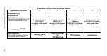
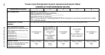
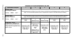
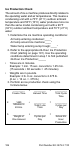
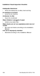
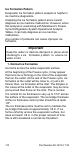
Table Of Contents
- General Information
- Installation
- Component Identification
- Maintenance
- Sequence of Operation
- Troubleshooting
- Safety Limits
- Control Board Testing
- Troubleshooting By Symptom
- Symptom #4
- Symptom #1 Ice Machine will not run
- Compressor Electrical Diagnostics
- Symptom #2 Low Production, Long Freeze
- Symptom #2 - Freeze Cycle Refrigeration System Operational Analysis Tables
- Freeze Cycle Refrigeration System Operational Analysis Table Procedures
- Before Beginning Service
- Ice Production Check
- Installation/Visual Inspection Checklist
- Water System Checklist
- Ice Formation Pattern
- Analyzing Discharge Pressure in the Freeze Cycle
- Analyzing Suction Pressure
- Single Expansion Valve Ice Machines Comparing Evaporator Inlet and Outlet Temperatures
- Multiple Expansion Valve Ice Machines Comparing Evaporator Inlet and Outlet Temperatures
- Harvest Valve Analysis
- Discharge Line Temperature Analysis
- Water Regulating Valve
- Final Analysis
- Harvest Problems
- Component Check Procedures
- Electrical Components
- Compressor Electrical Diagnostics
- Refrigeration Components
- Refrigerant Recovery/Evacuation
- System Contamination Clean-Up
- Specifications
- Charts
- Diagrams
- Wiring Diagrams
- Wiring Diagram Legend
- Wiring Diagrams Before Energy Efficient & EnergyStar Machines
- S320 Self Contained - 1 Phase
- S300/S420/S450/ S500 (after serial number 110074051) - Self Contained - 1 Phase
- S500 (before serial number 110074051) S600/S850/S1000/S1200- Self Contained- 1 Phase
- S850/S1000/S1200 - Self Contained - 3 Phase
- S500 Danfoss Compressor (after serial number 110074051) - Remote - 1 Phase
- S500 (before serial number 110074051)/ S600/S850/S1000/S1200 - Remote - 1 Phase
- S850/S1000/S1200 - Remote - 3 Phase
- S1400/S1600/S1800 - Self-Contained - 1 Phase
- S1400/S1600/S1800 - Self-Contained - 3 Phase
- S1400/S1600/S1800 - Remote - 1 Phase
- S1400/S1600/S1800 - Remote - 3 Phase
- Wiring Diagrams for Energy Efficient & EnergyStar Machines
- S300/S420/S450/S500 Self-Contained - 1 Phase
- S600/S850/S1000/S1200 Self-Contained - 1 Phase
- S850/S1000/S1200 Self-Contained - 3 Phase
- S1400/S1800 Self-Contained - 1 Phase
- S1400/S1800 Self-Contained - 3 Phase
- S3300 Water-Cooled - 3 phase
- S500 Remote - 1 Phase
- S600/S850/S1000/S1200 Remote - 1 Phase
- S850/S1000/S1200 Remote - 3 Phase
- S1400/S1800 Remote - 1 Phase
- S1400/S1800 Remote - 3 Phase
- Electronic Control Board
- Refrigeration Tubing Schematics
- Wiring Diagrams

104 Part Number 80-1479-3 7/10
Harvest Valve Temperature
Wait 5 minutes into the freeze
cycle.
Compare temperatures of
compressor discharge line and
harvest valve inlets.
One harvest valve
inlet is Hot
-and-
approaches the
temperature of a
Hot compressor
discharge line.
All harvest valve
inlets are Cool
enough to hold
and
the compressor
discharge line is
Hot.
All harvest valve
inlets are Cool
enough to hold
and-
the compressor
discharge line is
Cool
enough to hold
hand on.
All harvest valve
inlets are Cool
enough to hold
and-
the compressor
discharge line is
Hot.
All harvest valve
inlets are Cool
enough to hold
and-
the compressor
discharge line is
Cool
enough to hold
hand on.
Discharge Line
Temperature
Record freeze cycle discharge
line temperature at the end of the
freeze cycle
_________°F (°C)
Discharge line
temperature 150°F
(65°C)
or higher at the
end of the freeze
cycle
Discharge line
temperature
150°F (65°C)
or higher at the
end of the freeze
cycle
Discharge line
temperature
less than
150°F (65°C) at
the end of the
freeze cycle
or
Compressor
shell is frosted
Discharge line
temperature 150°F
(65°C) or higher at
the end of the
freeze cycle
Discharge line
temperature
less than
150°F (65°C) at
the end of the
freeze cycle
or
Compressor shell
is frosted
Final Analysis
Enter total number of boxes
checked in each column.
Harvest Valve
Leaking
Low On Charge
-Or-
TXV Starving
TXV Flooding Compressor
Harvest Pressure
Valve Leaking
S MODELS FOUR EXPANSION VALVES
Operational Analysis 1 2 3 4 5