Manitowoc S Model Ice Machines Technician’s Handbook This manual is updated as new information and models are released. Visit our website for the latest manual. www.manitowocice.
Safety Notices As you work on Manitowoc equipment, be sure to pay close attention to the safety notices in this handbook. Disregarding the notices may lead to serious injury and/or damage to the equipment. Throughout this handbook, you will see the following types of safety notices: ! Warning Text in a Warning b ox alerts yo u to a p otential personal injury si tuation. Be su re to read the Warning statement before proceeding, a nd w ork carefully.
NOTE: Text set off as a Note provides you with simple, but useful, extra information about the procedure you are performing. Read These Before Proceeding: ! Caution Proper i nstallation, ca re and ma intenance are essential for maximum performance and troublefree op eration of you r Manitowo c eq uipment. If you en counter prob lems not covered by this handbook, do no t procee d, contact Ma nitowoc Foodservice. We wi ll b e happy to p rovide assistance.
Table of Contents General Information Model Numbers . . . . . . . . . . . . . . . . . . . . . 9 How to Read a Model Number . . . . . . 10 Ice Cube Sizes . . . . . . . . . . . . . . . . . . . . . 10 Model/Serial Number Location . . . . . . . . 11 Energy Efficient Ice Machine Serial Breaks . . . . . . . . . . . . . . . . . . . . . . . 12 Ice Machine Warranty Information . . . . . 13 Owner Warranty Registration Card . . . 13 Commercial Warranty Coverage . . . . . 14 Residential Ice Machine Warranty . . . .
Removal from Service/Winterization . . . 57 Self-Contained Air-Cooled Ice Machines 57 Water-Cooled Ice Machines . . . . . . . . 58 Remote Ice Machines . . . . . . . . . . . . . 58 Sequence of Operation Self Contained Air or Water Cooled . . . . Single & Quad Evaporator Models . . . Safety Timers . . . . . . . . . . . . . . . . . . . . . . Safety Limits . . . . . . . . . . . . . . . . . . . . . . Remotes . . . . . . . . . . . . . . . . . . . . . . . 59 59 64 65 72 Troubleshooting Safety Limits . . . . . .
Component Check Procedures Electrical Components . . . . . . . . . . . . . . . 135 Main Fuse . . . . . . . . . . . . . . . . . . . . . . 135 ICE/OFF/CLEAN Toggle Switch . . . . . 136 Bin Switch . . . . . . . . . . . . . . . . . . . . . . 137 Cleaning the Ice Thickness or Water Level Probe . . . . . . . . . . . . . . . . . . . . . . . . . . 140 Water Level Control Circuitry . . . . . . . 141 Ice Thickness Probe (Harvest Initiation) . . . . . . . . . . . . . . . . . . . . . . . . . . . . . . .
Charts Cycle Times/24-Hour Ice Production/ Refrigerant Pressure Charts . . . . . . . . . . S300 Series . . . . . . . . . . . . . . . . . . . . S320 Series . . . . . . . . . . . . . . . . . . . . S420 Series . . . . . . . . . . . . . . . . . . . . S450 Series . . . . . . . . . . . . . . . . . . . . S500 Series . . . . . . . . . . . . . . . . . . . . S600 Series . . . . . . . . . . . . . . . . . . . . S850 Series . . . . . . . . . . . . . . . . . . . . S1000 Series . . . . . . . . . . . . . . . . . . .
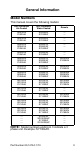
General Information Model Numbers This manual covers the following models: Self-Contained Air-Cooled Self-Contained Water-Cooled Remote SD0302A SY0304A SD0303W SY0305W ----- SD0322A SY0324A SD0323W SY0325W ----- SR0420A SD0422A SY0424A SR0421W SD0423W SY0425W ----- SD0452A SY0454A SD0453W SY0455W ----- SR0500A SD0502A SY0504A SR0501W SD0503W SY0505W SD0592N SY0594N SD0602A SY0604A SD0603W SY0605W SD0692N SY0694N SR0850A SD0852A SY0854A SR0851W SD0853W SY0855W SR0890N SD0892N SY0894N
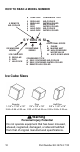
HOW TO READ A MODEL NUMBER 9 REMOTE AIR-COOLED # CUBE SIZE CONDENSER TYPE 0 1 2 3 4 5 REGULAR REGULAR DICE DICE HALF-DICE HALF-DICE AIR-COOLED WATER-COOLED AIR-COOLED WATER-COOLED AIR-COOLED WATER-COOLED S Y 1094 N SI ICE MACHINE MODEL ICE CUBE SIZE R REGULAR D DICE Y HALF DICE ADDITIONAL SPECS 3 PHASE M MARINE UNIT HP HIGH PRESSURE WATER VALVE SI AUCS-SI INCLUDED ICE MACHINE SERIES CONDENSER TYPE A SELF-CONTAINED AIR-COOLED W SELF-CONTAINED WATER-COOLED N REMOTE AIR-COOLED Ice Cube Sizes Regul
! Warning All Man itowoc ice ma chines re quire th e ice storage system (bin, dispenser, etc.) to incorporate an ice deflector. 48” w ide S Model ice mach ines re quire add ing Manitowoc Ice Deflector Kit K00 349 w hen installing wi th non-Manitowoc ice sto rage systems. 30” w ide S Model ice mach ines re quire add ing Manitowoc Ice Deflector Kit K00 347 w hen installing wi th non-Manitowoc ice sto rage systems.
Energy Efficient Ice Machine Serial Breaks Some specifications have changed with our release of more Energy Efficient machines. The following machines have a serial break to indicate when they became more Energy Efficient.
Ice Machine Warranty Information OWNER WARRANTY REGISTRATION CARD Warranty coverage begins the day the ice machine is installed. Important Complete and mail the OW NER WARRANTY REGISTRATION C ARD as soon as p ossible to validate the installation date. If the OWNER WARRANTY REGISTRATION CARD is not returned, Manitowoc will use the date of sale to the Manitowoc Distributor as the first day of warranty coverage for your new ice machine.
COMMERCIAL WARRANTY COVERAGE Manitowoc Ice, (hereinafter referred to as the "COMPANY") warrants for a period of thirty-six months from the installation date (except as limited below) that new ice machines manufactured by the COMPANY shall be free of defects in material or workmanship under normal and proper use and maintenance as specified by the COMPANY and upon proper installation and start-up in accordance with the instruction manual supplied with the ice machine.
The foregoing warranty shall not apply to (1) any part or assembly that has been altered, modified, or changed; (2) any part or assembly that has been subjected to misuse, abuse, neglect, or accidents; (3) any ice machine that has been installed and/or maintained inconsistent with the technical instructions provided by the COMPANY; or (4) any ice machine initially installed more than five years from the serial number production date.
RESIDENTIAL ICE MACHINE LIMITED WARRANTY WHAT DOES THIS LIMITED WARRANTY COVER? Subject to the exclusions and limitations below, Manitowoc Ice, Inc. (“Manitowoc”) warrants to the original consumer that any new ice machine manufactured by Manitowoc (the “Product”) shall be free of defects in material or workmanship for the warranty period outlined below under normal use and maintenance, and upon proper installation and startup in accordance with the instruction manual supplied with the Product.
WHAT ARE MANITOWOC ICE’S OBLIGATIONS UNDER THIS LIMITED WARRANTY? If a defect arises and Manitowoc receives a valid warranty claim prior to the expiration of the warranty period, Manitowoc shall, at its option: (1) repair the Product at Manitowoc’s cost, including standard straight time labor charges, (2) replace the Product with one that is new or at least as functionally equivalent as the original, or (3) refund the purchase price for the Product.
WHAT IS NOT COVERED? This limited warranty does not cover, and you are solely responsible for the costs of: (1) periodic or routine maintenance, (2) repair or replacement of the Product or parts due to normal wear and tear, (3) defects or damage to the Product or parts resulting from misuse, abuse, neglect, or accidents, (4) defects or damage to the Product or parts resulting from improper or unauthorized alterations, modifications, or changes; and (5) defects or damage to any Product that has not been inst
IN NO EVENT SHALL MANITOWOC OR ANY OF ITS AFFILIATES BE LIABLE TO THE CONSUMER OR ANY OTHER PERSON FOR ANY INCIDENTAL, CONSEQUENTIAL OR SPECIAL DAMAGES OF ANY KIND (INCLUDING, WITHOUT LIMITATION, LOSS OF PROFITS, REVENUE OR BUSINESS) ARISING FROM OR IN ANY MANNER CONNECTED WITH THE PRODUCT, ANY BREACH OF THIS LIMITED WARRANTY, OR ANY OTHER CAUSE WHATSOEVER, WHETHER BASED ON CONTRACT, TORT OR ANY OTHER THEORY OF LIABILITY.
This Page Intentionally Left Blank 20 Part Number 80-1479-3 7/10
Installation ! Warning PERSONAL INJURY POTENTIAL Remove a ll i ce machi ne p anels before lifting a nd installing. Location of Ice Machine The location selected for the ice machine head section must meet the following criteria. If any of these criteria are not met, select another location. • The location must be free of airborne and other contaminants. • Self contained air and water cooled - The air temperature must be at least 35°F (1.6°C), but must not exceed 110°F (43.4°C).
Ice Machine Clearance Requirements S300 Self-Contained Air-Cooled Self-Contained Water-Cooled Top/Sides 16" (40.6 cm) 8" (20.3 cm) Back 5" (12.7 cm) 5" (12.7 cm) S320/S450/S500/ S600/S850/S1000 Self-Contained Air-Cooled Water-Cooled and Remote* Top/Sides 8" (20.3 cm) 8" (20.3 cm) Back 5" (12.7 cm) 5" (12.7 cm) S420 Self-Contained Air-Cooled Water-Cooled and Remote* Top/Sides 12" (30.5 cm) 8" (20.3 cm) Back 5" (12.7 cm) 5" (12.
Ice Machine Heat of Rejection Heat of Rejection Series Ice Machine Air Conditioning* Peak S300 3,800 6,000 S320 3,800 6,000 S420/S450 7,000 9,600 S500 7,000 9,600 S600 9,000 13,900 S850 12,000 18,000 S1000 16,000 22,000 S1200 19,000 28,000 S1400 19,000 28,000 S1600 21,000 31,000 24,000 36,000 S1800 Energy Efficient Machines S300 5,000 S420/S450 5,900 6,000 6,900 S500 6,100 6,900 S850 13,000 16,000 S1000 17,700 21,000 S1200 20,700 24,500 S1400W 25,000 28
REMOTE CONDENSER LINE SET INSTALLATION Ice Machine Remote Single Circuit Condenser S500 JC0495 S600 S800 S1000 S1400 S1600 S1800 *Line Set RT RL JC0895 JC1395 Discharge Line 1/2" (1.27 cm) 1/2" (1.27 cm) Line Set* RT-20-R404A RT-35-R404A RT-50-R404A RT-20-R404A RT-35-R404A RT-50-R404A RL-20-R404A RL-35-R404A RL-50-R404A Liquid Line 5/16" (.79 cm) 3/8" (.
CALCULATING REMOTE CONDENSER INSTALLATION DISTANCES NOTE: Manitowoc warrants only complete new and unused remote packages. Warranty on the refrigeration system will be void if a new ice machine head section is connected to existing (used) tubing or condensers. Line Set Length The maximum length is 100' (30.5 m). The ice machine compressor must have the proper oil return. The receiver is designed to hold a charge sufficient to operate the ice machine in ambient temperatures between -20°F (-28.
Calculated Line Set Distance The maximum calculated distance is 150' (45.7 m). Line set rises, drops, horizontal runs (or combinations of these) in excess of the stated maximums will exceed compressor start-up and design limits. This will cause poor oil return to the compressor. Make the following calculations to make sure the line set layout is within specifications. 1. Insert the measured rise into the formula below. Multiply by 1.7 to get the calculated rise.
Maximum Line Set Distance Formula Step 1 Measured Rise ____ X 1.7 = ______Calculated Rise (35 ft. Max) Step 2 Measured Drop ____ X 6.6 = ______Calculated Drop (15 ft. Max.) Step 3 Measured Horizontal Distance = _________Horizontal (100 ft. Max.) Distance Step 4 Total Calculated Distance = ________Total Calculated (150 ft. Max.) Distance LENGTHENING OR REDUCING LINE SET LENGTHS In most cases, by routing the line set properly, shortening will not be necessary.
CONNECTING A LINE SET 1. Remove the dust caps from the line set, condenser and ice machine. 2. Apply refrigeration oil to the threads on the quick disconnect couplers before connecting them to the condenser. 3. Carefully thread the female fitting to the condenser or ice machine by hand. 4. Tighten the couplings with a wrench until they bottom out. 5. Turn an additional 1/4 turn to ensure proper brass-to-brass seating. Torque to the following specifications: Liquid Line Discharge Line 10-12 ft lb. (13.
Component Identification S Model Single Evaporator Models EVAPORATOR WATER DISTRIBUTION TUBE WATER TROUGH ICE THICKNESS CONTROL WATER CURTAIN REFRIGERATION ACCESS VALVES TOGGLE SWITCH CONTROL BOX WATER INLET LOCATION, THE WATER INLET VALVE IS LOCATED IN THE REFRIGERATION COMPARTMENT WATER LEVEL PROBE WATER PUMP Part Number 80-1479-3 7/10 29
WATER TROUGH ICE DAMPERS EVAPORATORS WATER LEVEL PROBE WATER PUMPS CONTROL BOX S Model Quad Evaporator Models Part Number 80-1479-3 7/10
Maintenance General Clean and sanitize the ice machine every six months for efficient operation. If the ice machine requires more frequent cleaning and sanitizing, consult a water care professional to test the water quality and recommend appropriate water treatment. An extremely dirty ice machine must be taken apart for cleaning and sanitizing. Manitowoc Ice Machine Cleaner and Sanitizer are the only products approved for use in Manitowoc ice machines.
Cleaning / Sanitizing Procedure ! Caution Use on ly Mani towoc app roved Ice Machi ne Cleaner and Sanitize r fo r this application (Manitowoc Clea ner p art n umber 9 4-0546-3 a nd Manitowoc Sanitizer part number 94-0565-3). It is a violation of Federal law to use these solutions in a man ner inconsistent with the ir la beling. Re ad and und erstand a ll l abels prin ted on bo ttles before use. CLEANING PROCEDURE ! Caution Do n ot mi x Clea ner a nd Sa nitizer sol utions together.
Step 3 Remove all ice from the bin. Step 4 Place the toggle switch in the CLEAN position. The water will flow through the water dump valve and down the drain. Wait until the water trough refills and water flows over the evaporator, then add the proper amount of ice machine cleaner.
PARTS REMOVAL FOR CLEANING/SANITIZING Single Evaporator Ice Machines A. Remove the water curtain • • Gently flex the curtain in the center and remove it from the right side. Slide the left pin out. B. Remove the ice thickness probe • Compress the hinge pin on the top of the ice thickness probe. • Pivot the ice thickness probe to disengage one pin then the other. The ice thickness probe can be cleaned at this point without complete removal.
Quad Evaporator Ice Machines A.Remove the water trough shield. • • • Grasp the water trough shield in the center and the left end. Flex the water trough shield in the center and pull the left end forward until clear of the side wall. Repeat for the right end. Pull water trough shield forward to remove. B. Remove Splash Shields. • • Grasp the top center of splash shields. Lift up and then out. C. Remove ice thickness probe. • • Compress the hinge pin on the top of the ice thickness probe.
C D B A E 36 Part Number 80-1479-3 7/10
Step 7 Mix a solution of cleaner and warm water. Depending upon the amount of mineral buildup, a larger quantity of solution may be required. Use the ratio in the table below to mix enough solution to thoroughly clean all parts. Solution Type Cleaner Water Mixed With 1 gal. (4 l) 16 oz (500 ml) cleaner Step 8 Use 1/2 of the cleaner/water mixture to clean all components.
Step 12 Use 1/2 of the sanitizer/water solution to sanitize all foodzone surfaces of the ice machine and bin (or dispenser). Use a spray bottle to liberally apply the solution. When sanitizing, pay particular attention to the following areas: • Side walls • Base (area above water trough) • Evaporator plastic parts - including top, bottom and sides • Bin or dispenser Do not rinse the sanitized areas. Step 13 Replace all removed components. Step 14 Wait 30 minutes.
Step 15 Reapply power to the ice machine and place the toggle switch in the CLEAN position. Step 16 Wait until the water trough refills and water flows over the evaporator (approximately 3 minutes). Add the proper amount of Manitowoc Ice Machine Sanitizer to the water trough by pouring between the water curtain/splash shields and evaporator..
Procedure to Clean Heavily Scaled Ice Machines Ice machines that are heavily scaled or have not been cleaned on a regular basis will need to run this procedure. GENERAL Clean and sanitize the ice machine every six months for efficient operation. If the ice machine requires more frequent cleaning and sanitizing, consult a qualified service company to test the water quality and recommend appropriate water treatment. The ice machine must be taken apart for cleaning and sanitizing.
Ice machine cleaner is used to remove lime scale and mineral deposits. Ice machine sanitizer disinfects and removes algae and slime. Step 1 Set the toggle switch to the OFF position after ice falls from the evaporator at the end of a Harvest cycle. Or, set the switch to the OFF position and allow the ice to melt off the evaporator. ! Caution Never use anythin g to fo rce ice fro m the evaporator. Damage may result. Step 2 Remove top cover.
Step 5 Wait until the clean cycle is complete (approximately *35 minutes). then place the toggle switch in the OFF position and disconnect power to the ice machine (and dispenser when used) NOTE: *S3300 Only - 80 minutes.. ! Warning Disconnect the electric power to the ice machine at the electric service switch box. Step 6 Remove parts for cleaning. Please refer to the proper parts removal for your ice machine. Single Evaporator Ice Machines - page 43. Quad Evaporator Ice Machines - page 46.
PARTS REMOVAL FOR CLEANING/SANITIZING Single Evaporator Ice Machines A. Remove the water curtain • • Gently flex the curtain in the center and remove it from the right side. Slide the left pin out. B. Remove the ice thickness probe • • Compress the hinge pin on the top of the ice thickness probe. Pivot the ice thickness probe to disengage one pin then the other. The ice thickness probe can be cleaned at this point without complete removal.
E. Remove the water level probe • • • • Pull the water level probe straight down to disengage. Lower the water level probe until the wiring connector is visible. Disconnect the wire lead from the water level probe. Remove the water level probe from the ice machine. F. Remove the water pump. • • • • Grasp pump and pull straight down on pump assembly until water pump disengages and electrical connector is visible. Disconnect the electrical connector. Remove the water pump assembly from ice machine.
C. B. A. G. E. F. D.
Quad Evaporator Ice Machines A. Remove panels • • Remove both front panels Remove top panel B. Remove front evaporator shield. • • Remove four quarter turn connectors Remove splash shield C. Remove left and right evaporator top covers. • • Remove two thumbscrews from the front of each evaporator top cover. Lift front of cover, pull forward to remove. D. Remove Splash Shields. • Grasp the top center of splash shields. • Lift up and then out.
F. Remove distribution tubes. • Distribution tube thumbscrews are retained to prevent loss. Loosen thumbscrews but do not pull thumbscrews out of distribution tube. • Loosen the two outer screws and pull forward on the distribution tube to release from slip joint. • Disassemble distribution tube by loosening the two (2) middle thumbscrews and dividing the distribution tube into two pieces. NOTE: Each evaporator has a distribution tube that must be removed - total of four distribution tubes. G.
A C D F G I E B H A 48 Part Number 80-1479-3 7/10
Step 7 Mix a solution of cleaner and warm water. Depending upon the amount of mineral buildup, a larger quantity of solution may be required. Use the ratio in the table below to mix enough solution to thoroughly clean all parts. Solution Type Water Mixed With Cleaner 1 gal. (4 l) 16 oz (500 ml) cleaner Step 8 Use 1/2 of the cleaner/water mixture to clean all components.
bin (or dispenser). Use a cloth or sponge to liberally apply the solution. When sanitizing, pay particular attention to the following areas: • Side walls • Base (area above water trough) • Evaporator plastic parts - including top, bottom and sides • Bin or dispenser Do not rinse the sanitized areas. Step 13 Replace all removed components. Step 14 Reapply power to the ice machine and place the toggle switch in the CLEAN position.
Solution Type Water Mixed With Sanitizer 6 gal. (23 l) 4 oz (120 ml) sanitizer Step 19 Use 1/2 of the sanitizer/water solution to sanitize all removed components. Use a cloth or sponge to liberally apply the solution to all surfaces of the removed parts or soak the removed parts in the sanitizer/water solution. Do not rinse parts after sanitizing. Step 20 Use 1/2 of the sanitizer/water solution to sanitize all foodzone surfaces of the ice machine and bin (or dispenser).
Ice Thickness Probe & Water Level Probe Clean the probes using the following procedure. 1. Mix a solution of Manitowoc ice machine cleaner and water (2 ounces of cleaner to 16 ounces of water) in a container. 2. Soak probes in container of cleaner/water solution while disassembling and cleaning water circuit components (soak probes for 10 minutes or longer). 3. Clean all probe surfaces including all plastic parts (do not use abrasives). Verify all cavities are clean.
Water Inlet Valve The water inlet valve normally does not require removal for cleaning. Refer to “Water System Checklist” page 109, if you are troubleshooting water related problems. 1. When the ice machine is off, the water inlet valve must completely stop water flow into the machine. Watch for water flow. When the ice machine is on, the water inlet valve must allow the proper water flow through it. Set the toggle switch to ON. Watch for water flow into the ice machine.
Water Dump Valve The water dump valve normally does not require removal for cleaning. To determine if removal is necessary: 1. Locate the water dump valve. 2. Set the toggle switch to ICE. 3. While the ice machine is in the freeze mode, check the water trough to determine if the dump valve is leaking. If there is no or little water in the water trough (during the freeze cycle) the dump valve is leaking. A. If the dump valve is leaking, remove, disassemble and clean it. B.
NOTE: During cleaning, do not stretch or damage the spring. 1. Remove the tubing from the dump valve by twisting the clamps off. 2. Remove the valve body, twist off.
Drain Line Check Valve The drain line check valve (not used on all models) should be inspected and cleaned, whenever the ice machine is cleaned. CHECK VALVE ASSEMBLY CHECK VALVE 1. Remove check valve and tube assembly. A. Tip assembly to right until tubing disengages. B. Lift up on assembly to remove. 2. Remove insulation from check valve assembly. 3. Remove vinyl tubing from top of check valve. 4. Soak in cleaner solution 10 minutes, and then flush with water to remove debris.
Removal from Service/Winterization General Special precautions must be taken if the ice machine is to be removed from service for an extended period of time or exposed to ambient temperatures of 32°F (0°C) or below. ! Caution If water is al lowed to remain in the ice ma chine in freezing temperatures, se vere damag e to some components could resu lt. Damage of thi s na ture is not covered by the warranty. Follow the applicable procedure below. SELF-CONTAINED AIR-COOLED ICE MACHINES 1.
WATER-COOLED ICE MACHINES 1. Perform steps 1-6 under “Self-Contained AirCooled Ice Machines.” 2. Disconnect the incoming water and drain line from the water-cooled condenser. 3. Insert a large screwdriver between the bottom spring coils of the water regulating valve. Pry upward to open the valve. SV1624 4. Hold the valve open and blow compressed air through the condenser until no water remains. REMOTE ICE MACHINES 1. Move the ICE/OFF/CLEAN switch to OFF. 2.
Sequence of Operation Self Contained Air or Water Cooled SINGLE & QUAD EVAPORATOR MODELS NOTE: The toggle switch must be in the ice position and the water curtain/ice dampers must be in place on the evaporator before the ice machine will start. Initial Start-Up or Start-Up After Automatic Shut-Off 1. Water Purge Before the refrigerant compressor starts, the water pump and water dump solenoid energize to purge the ice machine of old water.
Freeze Sequence 3. Prechill The compressor lowers the temperature of the evaporator(s) before the water pump is energized. The water fill valve will remain energized until water contacts the water level probe. Energized Control Board LightsSingle Evaporators = Left Bin (green) Quad Evaporators = All Curtain Switches (green), Water Solenoid (red), Liquid Solenoid (red) 4. Freeze The water pump(s) energizes and water flows over the evaporator.
Harvest Sequence 5. Water Purge The air compressor (when used) and the harvest valve(s) open at the beginning of the water purge to divert hot refrigerant gas into the evaporator. The water pump continues to run, and the water dump valve energizes to purge the water in the water trough. Single evaporator models energize the water fill valve for the last 15 seconds of the water purge cycle.
6. Harvest The air compressor (when used) remains energized and the harvest valve(s) remains open. The refrigerant gas warms the evaporator causing the cubes to slide, as a sheet, off the evaporator and into the storage bin.
Automatic Shut-Off 7. Automatic Shut-Off When the storage bin is full at the end of a harvest sequence, the sheet of cubes fails to clear the water curtain/ice damper and will hold it open. After the water curtain/ice damper is held open for 30 seconds, the ice machine shuts off. The ice machine remains off for 3 minutes before it can automatically restart.
Safety Timers The control board has the following non-adjustable safety timers: • The ice machine is locked into the freeze cycle for 6 minutes before a harvest cycle can be initiated. Freeze lock is bypassed after moving the toggle switch from OFF to ICE position for the first cycle only. • The maximum freeze time is 60 minutes at which time the control board automatically initiates a harvest sequence (steps 5 & 6). • The maximum harvest time is 3.
Safety Limits Safety limits are stored and indicated by the control board after three cycles. The number of cycles required to stop the ice machine varies for each safety limit. • Safety Limit 1 - If the freeze time reaches 60 minutes, the control board automatically initiates a harvest cycle. If 6 consecutive 60-minute freeze cycles occur, the ice machine stops • Safety Limit 2 single evaporator models - If the harvest time reaches 3.
Safety Limit Stand-By Mode (Quad Evaporators Only) The first time a safety limit shut down occurs, (three consecutive long freeze or harvest cycles) the ice machine will turn off for 60 minutes (Stand-By Mode). During the Stand-By Mode the harvest light will be flashing continuously and a safety limit indication can be viewed. After 60 minutes the ice machine will automatically restart to see if the problem re-occurs.
Warm Water Rinse Cycle Single evaporator models only - Closing the back of the evaporator allows ice to build up on the rear of the evaporator and the plastic evaporator frame parts. After 200 freeze/harvest cycles have been completed the control board will initiate a warm water rinse. After the 200th harvest cycle ends: • The Clean and Harvest LEDs energize to indicate the ice machine is in a warm water rinse. • The compressor and harvest valve remain energized. • The water pump energizes.
Self Contained Air & Water-Cooled Single Evaporator Model Energized Parts Chart Ice Making Sequence of Operation Water Pump Harvest Valve(s) Water Inlet Valve Water Dump Valve Contactor Coil Compressor Condenser Fan Motor Length of Time Off On Off Off Off 45 Seconds On Off On On Off On On 35 sec. Start-Up 1. Water Purge Air Pump(s)* Off On On 10 sec. On Part Number 80-1479-3 7/10 2. Refrigeration System Start-up Off On Off May Cycle Freeze Sequence 3.
Part Number 80-1479-3 7/10 Self Contained Air & Water-Cooled Single Evaporator Model Energized Parts Chart (Continued) Ice Making Sequence of Operation Water Pump Harvest Valve(s) Air Pump(s)* Water Inlet Valve Water Dump Valve Contactor Coil Compressor On On On Length of Time May Cycle Factory Set at 45 Seconds May Cycle On/Off Bin Switch Activation Off Until Bin Switch Re-closes & 3 min. delay 30 sec. Harvest Sequence Off On On On 6. Harvest Off On On Off Off On On 7.
Self Contained Water-Cooled Quad Evaporator Model Energized Parts Chart Ice Making Sequence of Operation Water Pumps Harvest Valves Air Pumps Water Inlet Valve Water Dump Valves Contactor Coil Compressor On Off Off Off On Off Off Start-Up 1. Water Purge Part Number 80-1479-3 7/10 2.
Part Number 80-1479-3 7/10 Self Contained Water-Cooled Quad Evaporator Model Energized Parts Chart (Continued) Ice Making Sequence of Operation Water Dump Valves Contactor Coil Compressor Length of Time from 30-45 seconds On On On Factory Set at 30 Seconds On Off Off On On Bin Switch Activation Off Off Off Off Off Until Bin Switch Re-closes & 3 min. delay expires Water Pumps Harvest Valves Air Pumps Water Inlet Valve On On On 6. Harvest Off On 7.
REMOTES Single Evaporator Models NOTE: The toggle switch must be in the ice position and the water curtain must be in place on the evaporator before the ice machine will start. Initial Start-Up or Start-Up After Automatic Shut-Off 1. Water Purge Before the compressor starts, the water pump and water dump solenoid are energized for 45 seconds, to completely purge the ice machine of old water. This feature ensures that the ice making cycle starts with fresh water.
2. Refrigeration System Start-Up The compressor and liquid line solenoid valve energize after the 45 second water purge and remain on throughout the entire Freeze and Harvest Sequences. The water fill valve is energized at the same time as the compressor. It remains on until the water level sensor closes for 3 continuous seconds, or until a six-minute time period has expired. The harvest valve and HPR solenoid valves remain on for 5 seconds during initial compressor start-up and then shut off.
Freeze Sequence 3. Prechill The compressor is on for 30 seconds (60 seconds initial cycle) prior to water flow, to prechill the evaporator. Energized Control Board LightsLeft Bin (green) 4. Freeze The water pump restarts after the prechill. An even flow of water is directed across the evaporator and into each cube cell, where it freezes. The water fill valve will cycle on and then off one more time to refill the water trough.
Harvest Sequence 5. Water Purge The water pump continues to run, and the water dump valve energizes for 45 seconds to purge the water in the sump trough. The water fill valve energizes (turns on) and de-energizes (turns off) strictly by time. The water fill valve energizes for the last 15 seconds of the 45-second water purge. The water purge must be at the factory setting of 45 seconds for the fill valve to energize during the last 15 seconds of the Water Purge.
Automatic Shut-Off 7. Automatic Shut-Off When the storage bin is full at the end of a harvest sequence, the sheet of cubes fails to clear the water curtain and will hold it open. After the water curtain is held open for 30 seconds, the ice machine shuts off. The ice machine remains off for 3 minutes before it can automatically restart. The ice machine remains off until enough ice has been removed from the storage bin to allow the ice to drop clear of the water curtain.
Part Number 80-1479-3 7/10 Remote Air-Cooled Single Evaporator Model Energized Parts Chart Ice Making Sequence of Operation Water Pump Harvest Valve (Left) HPR Valve Harvest Valve (Right) (When Used) Air Comp. (When Used) Water Inlet Valve Water Dump Valve Contactor Coil Liquid Line Solenoid Compressor Condenser Fan Motor Length of Time On On On 35 sec. Off 10 sec. On.
Remote Air-Cooled Single Evaporator Model Energized Parts Chart (Continued) Water Pump Harvest Valve (Left) HPR Valve Harvest Valve (Right) (When Used) Air Comp. (When Used) On On On On After 35 sec. 6. Harvest Off On On On 7. Automatic Shut-Off Off Off Off Off Ice Making Sequence of Operation Harvest Sequence 5.
This Page Intentionally Left Blank Part Number 80-1479-3 7/10 79
This Page Intentionally Left Blank 80 Part Number 80-1479-3 7/10
Troubleshooting Safety Limits In addition to standard safety controls, the control board has built in safety limit controls which protect the ice machine from major component failures. Use the following procedures to determine if the control board contains a safety limit indication. 1. Move the toggle switch to OFF. 2. Move the toggle switch back to ICE. 3. Watch the safety limit lights/harvest light on the control board.
QUAD EVAPORATOR MACHINES ONLY When a safety limit condition causes the ice machine to stop, the harvest light on the control board continually flashes on and off. Use the following procedures to determine which safety limit has stopped the ice machine. 1. Move the toggle switch to OFF. 2. Move the toggle switch back to ICE. 3. Watch the harvest light. It will flash one or two times, corresponding to safety limits 1 and 2, to indicate which safety limit stopped the ice machine.
Safety Limit Stand-By Mode: The first time a safety limit shut down occurs, (three consecutive long freeze or harvest cycles) the ice machine will turn off for 60 minutes (Stand-By Mode). During the Stand-By Mode the harvest light will be flashing continuously and a safety limit indication can be viewed. After 60 minutes the ice machine will automatically restart to see if the problem re-occurs.
ANALYZING WHY A SAFETY LIMIT STOPPED THE ICE MACHINE According to the refrigeration industry, a high percentage of compressors fail as a result of external causes. These can include: flooding or starving expansion valves, dirty condensers, water loss to the ice machine, etc. The safety limits protect the ice machine (primarily the compressor) from external failures by stopping ice machine operation before major component damage occurs. The safety limit system is similar to a high pressure cut-out control.
SAFETY LIMIT #1 Water System 1. Water supply to machine is being interrupted 2. Water leaking down the drain during freeze (dump valve or water tracking into condensate tray) 3. Water tracking into bin 4. Uneven water flow over evaporator 5. Water pump not pumping Electrical System 1. Improper voltage (low) 2. Ice thickness probe adjustment too thick 3. Water level probe open / dirty 4. Water inlet valve failure 5. Contactor failure 6.
SAFETY LIMIT #2 Water System 1. Ice thickness control probe is dirty causing a premature harvest with no ice on the plate. page 149 2. Dirty evaporator causing a long harvest and ice melt out. page 131 Electrical System 1. Ice thickness probe adjustment too close 2. Bin switch failed closed 3. Harvest valve not energizing 4. Quad Evaporator Only - Harvest pressure solenoid valve not energizing. Refrigeration System 1. Non-Manitowoc components 2. Incorrect refrigerant charge 3. TXV flooding 4.
SAFETY LIMIT #3 Water System 1. Water supply to machine is being interrupted 2. Water leaking down the drain during freeze (dump valve or water tracking into condensate tray) 3. Water tracking into bin 4. Uneven water flow over evaporator 5. Water pump not pumping Electrical System 1. Water level probe prematurely statisfied 2. Water inlet valve failure 3. Water pump failure Refrigeration System 1. Low on Refrigerant 2.
Control Board Testing All replacement S Model control boards and ice machines with serial numbers larger than 110924847 have a control board that includes a diagnostic test cycle. The control board can be identified by the blue printed circuit board and a push button switch on the bottom left corner labeled “service mode”. CONTROL BOARD TEST CYCLE 1. Place the toggle switch in the ice position. 2. Press and hold the test button for 5 seconds. 3. The control board memory is cleared. A.
Troubleshooting By Symptom The troubleshooting procedures follow flow charts. There are four symptoms, the symptom that you are experiencing will determine which flow chart to use. The flow chart asks yes andno questions to determine the problem. The flow chart will direct you to a procedure to correct the problem. Traditional remote and self contained models use seperate charts.
SYMPTOM #1 ICE MACHINE WILL NOT RUN Ice Machine Stops Running or Has a History of Shutting Down NO Does ice machine run in CLEAN? Part Number 80-1479-3 7/10 NO Refer to “Diagnosing an Ice Machine that Will Not Run” YES Control board has energized lights? NO YES Does the ice machine start when toggle switch is moved to ICE? YES Continued on Next Page...
Part Number 80-1479-3 7/10 YES YES Are Water Curtain/Ice Dampers in place? NO Which light flashed immediately after resetting the toggle switch? YES Install Water Curtain/ Ice Dampers Replace the Water Curtain/ Ice Dampers SL1/ Harvest (once) NO Refer to Safety Limit #1 Long Freeze Cycle Are Water Curtain/Ice Damper magnets attached? SL2/ Harvest (twice) Refer to Safety Limit #2 Long Harvest Cycle Harvest (3 times) Refer to Safety Limit #3 Low Pressure YES Run machine & check for Normal Operati
COMPRESSOR ELECTRICAL DIAGNOSTICS The compressor does not start or will trip repeatedly on overload. Check Resistance (Ohm) Values NOTE: Compressor windings can have very low ohm values. Use a properly calibrated meter. Perform the resistance test after the compressor cools. The compressor dome should be cool enough to touch (below 120°F/49°C) to assure that the overload is closed and the resistance readings will be accurate. SINGLE PHASE COMPRESSORS 1.
CHECK MOTOR WINDINGS TO GROUND Check continuity between all three terminals and the compressor shell or copper refrigeration line. Scrape metal surface to get good contact. If continuity is present, the compressor windings are grounded and the compressor should be replaced. COMPRESSOR DRAWING LOCKED ROTOR To determine if the compressor is seized, check the amp draw while the compressor is trying to start. The two likely causes of this are a defective starting component and a mechanically seized compressor.
SYMPTOM #2 LOW PRODUCTION, LONG FREEZE Ice Machine has a Long Freeze Cycle. Ice Formation is Thick or Thin Ice Fill on Top or Bottom of Evaporator or Low Production How to Use the Freeze Cycle Refrigeration System Operational Analysis Table GENERAL These tables must be used with charts, checklists and other references to eliminate refrigeration components not listed on the tables and external items and problems which can cause good refrigeration components to appear defective.
PROCEDURE Step 1 Complete the “Operation Analysis” column. Read down the left “Operational Analysis” column. Perform all procedures and check all information listed. Each item in this column has supporting reference material to help analyze each step. While analyzing each item separately, you may find an “external problem” causing a good refrigerant component to appear bad. Correct problems as they are found. If the operational problem is found, it is not necessary to complete the remaining procedures.
SYMPTOM #2 - FREEZE CYCLE REFRIGERATION SYSTEM OPERATIONAL ANALYSIS TABLES S MODELS SINGLE EXPANSION VALVE Operational Analysis Ice Production Installation and Water System Ice Formation Pattern Part Number 80-1479-3 7/10 Freeze Cycle Discharge Pressure _______ ______ ______ 1 minute Middle End into cycle 1 2 3 4 Air-Temperature Entering Condenser_____________ Water Temperature Entering Ice Machine_________ Published 24 hour ice production________________ Calculated (actual) ice production_______
Part Number 80-1479-3 7/10 S MODELS SINGLE EXPANSION VALVE Operational Analysis 1 2 3 4 If suction pressure is High or Low refer to freeze cycle high or low suction pressure problem checklist Freeze Cycle page 115 to eliminate problems and/or components not listed on this table before proceeding. Suction Pressure Suction pressure is Suction pressure is Suction pressure is _______ ______ _____ Suction pressure is High Low or Normal High High 1 minute Middle End Wait 5 minutes into the freeze cycle.
S MODELS SINGLE EXPANSION VALVE Part Number 80-1479-3 7/10 Operational Analysis 1 2 3 4 Wait 5 minutes into the freeze cycle. Compare temperatures of compressor discharge line and harvest valve inlet. The harvest valve inlet is Hot -andapproaches the temperature of a Hot compressor discharge line. The harvest valve inlet is Cool enough to hold hand on -andthe compressor discharge line is Hot.
Part Number 80-1479-3 7/10 Freeze Cycle Refrigeration System Operational Analysis Tables S MODELS DUAL EXPANSION VALVE Operational Analysis Ice Production Installation and Water System Ice Formation Pattern Left Side_______________ Right Side______________ 99 Freeze Cycle Discharge Pressure _______ ______ ______ 1 minute Middle End into cycle 1 2 3 4 Air-Temperature Entering Condenser_____________ Water Temperature Entering Ice Machine_________ Published 24 hour ice production________________ Calc
S MODELS DUAL EXPANSION VALVE Operational Analysis Freeze Cycle Suction Pressure _______ ______ _____ 1 minute Middle End Part Number 80-1479-3 7/10 Wait 5 minutes into the freeze cycle. Compare temperatures of compressor discharge line and both harvest valve inlets. 1 2 3 4 If suction pressure is High or Low refer to freeze cycle high or low suction pressure problem checklist page 115 to eliminate problems and/or components not listed on this table before proceeding.
Part Number 80-1479-3 7/10 S MODELS DUAL EXPANSION VALVE Operational Analysis Discharge Line Temperature Record freeze cycle discharge line temperature at the end of the freeze cycle 1 2 3 4 Discharge line temp. 150°F (65°C) or higher at the end of the freeze cycle Discharge line temp. 150°F (65°C) or higher at the end of the freeze cycle Discharge line temp. less than 150°F (65°C) at the end of the freeze cycle Discharge line temp.
Freeze Cycle Refrigeration System Operational Analysis Tables S MODELS FOUR EXPANSION VALVES Operational Analysis 1 2 3 4 5 Ice Production Ambient Air-Temperature_____________ Water Temperature Entering Ice Machine_________ Published 24 hour ice production________________ Calculated (actual) ice production_______________ NOTE: The ice machine is operating properly if the ice fill patterns is normal and ice production is within 10% of charted capacity.
Part Number 80-1479-3 7/10 S MODELS FOUR EXPANSION VALVES Operational Analysis Freeze Cycle Discharge Pressure _____ 1 minute ______ Middle Freeze Cycle Suction Pressure _____ 1 minute ______ Middle _____ End _____ End 1 3 4 5 If discharge pressure is High or Low refer to freeze cycle high or low discharge pressure problem checklist page 112 and eliminate problems and/or components not listed on this table before proceeding.
S MODELS FOUR EXPANSION VALVES Operational Analysis Harvest Valve Temperature Wait 5 minutes into the freeze cycle. Compare temperatures of compressor discharge line and harvest valve inlets. Part Number 80-1479-3 7/10 Discharge Line Temperature Record freeze cycle discharge line temperature at the end of the freeze cycle 1 2 3 One harvest valve inlet is Hot -andapproaches the temperature of a Hot compressor discharge line.
FREEZE CYCLE REFRIGERATION SYSTEM OPERATIONAL ANALYSIS TABLE PROCEDURES The following is the procedures for completing each step of the Freeze Cycle Refrigeration System Operational Analysis Tables. Each procedure must be performed exactly for the table to work correctly. Before Beginning Service Ice machines may experience operational problems only during certain times of the day or night. A machine may function properly while it is being serviced, but malfunctions later.
Ice Production Check The amount of ice a machine produces directly relates to the operating water and air temperatures. This means a condensing unit with a 70°F (21°C) outdoor ambient temperature and 50°F (10°C) water produces more ice than the same model condensing unit with a 90°F (32°C) outdoor ambient temperature and 70°F (21°C) water. 1. Determine the ice machine operating conditions: Air temp entering condenser:____° Air temp around ice machine:____° Water temp entering sump trough:____° 2.
Weighing the ice is the only 100% accurate check. However, if the ice pattern is normal and the 1/8 in. thickness is maintained, the ice slab weights listed with the 24-Hour Ice Production Charts may be used. 4. Compare the results of step 3 with step 2. Ice production checks that are within 10% of the chart are considered normal. If they match closely, determine if: • Another ice machine is required. • More storage capacity is required.
Installation/Visual Inspection Checklist Inadequate Clearances • Check all clearances on sides, back and top.
Water System Checklist A water-related problem often causes the same symptoms as a refrigeration system component malfunction. Water system problems must be identified and eliminated prior to replacing refrigeration components. Water area (evaporator) is dirty • Clean as needed Water inlet pressure not between 20 and 80 psig (1-5 Bar, 138-552 kPa).
Ice Formation Pattern Evaporator ice formation pattern analysis is helpful in ice machine diagnostics. Analyzing the ice formation pattern alone cannot diagnose an ice machine malfunction. However, when this analysis is used along with Manitowoc’s Freeze Cycle Refrigeration System Operational Analysis Tables, it can help diagnose an ice machine malfunction. Any number of problems can cause improper ice formation.
2. Extremely Thin at Evaporator Outlet There is no ice, or a considerable lack of ice formation, at the outlet of the evaporator. Examples: No ice at all on the outlet half of the evaporator, but ice forms on the inlet half of the evaporator. Or, the ice at the outlet of the evaporator reaches 1/8 in. to initiate a harvest, but the inlet of the evaporator already has 1/2 in. to 1 in. of ice formation. 3.
Analyzing Discharge Pressure in the Freeze Cycle 1. Determine the ice machine operating conditions: Air temp. entering condenser______ Air temp. around ice machine______ Water temp. entering sump trough______ 2. Refer to Operating Pressure table (starting on page 191) for ice machine being checked. Use the operating conditions determined in step 1 to find the published normal discharge pressures. Freeze Cycle______ Harvest Cycle______ 3. Perform an actual discharge pressure check.
FREEZE CYCLE DISCHARGE PRESSURE HIGH CHECKLIST Improper Installation • Refer to “Installation/Visual Inspection Checklist” (page 108) Air Condenser • Dirty condenser filter • Dirty condenser fins • High inlet air temperature (Self contained 110°F/ 43°C max. Remote 120°F/49°C max.). • Condenser discharge air recirculation • Defective fan cycling control (page 167) • Defective fan motor • Defective head pressure control valve {Remotes} (page 164) Water Condenser • Low water pressure [20 psig (138 kPa) min.
FREEZE CYCLE DISCHARGE PRESSURE LOW CHECKLIST Improper Installation • Refer to “Installation/Visual Inspection Checklist” (page 108) Air Cooled Condensers • Defective head pressure control valve, won’t bypass (page 164) • Defective fan cycle control, stuck closed (page 167) Water Cooled Condensers • Water Regulating Valve out of adjustment • Water Regulating Valve Defective Other • Undercharged • Wrong type of refrigerant • Non-Manitowoc components in system 114 Part Number 80-1479-3 7/10
Analyzing Suction Pressure The suction pressure gradually drops throughout the Freeze cycle. The actual suction pressure (and drop rate) changes as the air and water temperature entering the ice machine changes. These variables also determine the Freeze cycle times. To analyze and identify the proper suction pressure drop throughout the Freeze cycle, compare the published suction pressure to the published Freeze cycle time. NOTE: Analyze discharge pressure before analyzing suction pressure.
Suction Pressure High Checklist Improper Installation • Refer to “Installation/Visual Inspection Checklist” page 108 Discharge Pressure • Discharge pressure is too high and is affecting low side – refer to “Freeze Cycle Discharge Pressure High Checklist” (page 113) Improper Refrigerant Charge • Overcharged (also see “Freeze Cycle Discharge Pressure High Checklist” page 113) • Wrong type of refrigerant Components • Harvest valve leaking - continue the table • Harvest pressure solenoid valve leaking - continu
SUCTION PRESSURE LOW CHECKLIST Improper Installation • Refer to “Installation/Visual Inspection Checklist” (page 108) Discharge Pressure • Discharge pressure is too low and is affecting low side – refer to “Freeze Cycle Discharge Pressure High Checklist” (page 113) Improper Refrigerant Charge • Undercharged • Wrong type of refrigerant Other • Non-Manitowoc components in system • Improper water supply over evaporator – refer to “Water System Checklist” (page 109) • Restricted/plugged liquid line drier • Rest
Single Expansion Valve Ice Machines Comparing Evaporator Inlet and Outlet Temperatures NOTE: This procedure will not work on dual or Quad expansion valve ice machines. The temperatures of the suction lines entering and leaving the evaporator alone cannot diagnose an ice machine. However, comparing these temperatures during the freeze cycle, along with using Manitowoc’s Freeze Cycle Refrigeration System Operational Analysis Table, can help diagnose an ice machine malfunction.
Multiple Expansion Valve Ice Machines Comparing Evaporator Inlet and Outlet Temperatures The temperatures of the suction lines entering and leaving the evaporator alone cannot diagnose an ice machine. However, comparing these temperatures during the freeze cycle, along with using Manitowoc’s Freeze Cycle Refrigeration System Operational Analysis Table, can help diagnose an ice machine malfunction. The temperature difference between evaporator outlets vary throughout the freeze cycle.
Harvest Valve Analysis Symptoms of a harvest valve remaining partially open during the freeze cycle can be similar to symptoms of either an expansion valve or compressor problem. The best way to diagnose a harvest valve is by using Manitowoc’s Ice Machine Freeze Cycle Refrigeration System Operational Analysis Table. Use the following procedure and table to help determine if a harvest valve is remaining partially open during the freeze cycle. 1. Wait five minutes into the freeze cycle. 2.
Findings Comments The inlet of the harvest valve is cool enough to touch and the compressor discharge line is hot. This is normal as the discharge line should always be too hot to touch and the harvest valve inlet, although too hot to touch during harvest, should be cool enough to touch after 5 minutes into the freeze cycle. Cool & Hot The inlet of the harvest valve is hot and approaches the temperature of a hot compressor discharge line.
Discharge Line Temperature Analysis GENERAL Knowing if the discharge line temperature is increasing, decreasing or remaining constant can be an important diagnostic tool. Compressor discharge line temperature on a normally operating ice machine steadily increases throughout the freeze cycle. Ambient air temperatures affect the discharge line temperature. Higher ambient air temperatures at the condenser and/or higher inlet water temperature = higher discharge line temperatures at the compressor.
Water Regulating Valve Problem (Freeze Cycle) Valve not maintaining discharge pressure. • Valve incorrectly set, dirty or defective. Adjust valve to 240 psig, clean or replace valve. Discharge pressure extremely high; Liquid line entering receiver feels hot. • Water regulating valve incorrectly set or not opening. Verify Head Pressure Control Valve operation before changing water regulating valve. Discharge pressure low, Liquid line entering receiver feels warm to hot. • Ice machine low on charge.
Final Analysis The column with the highest number of check marks identifies the refrigeration problem. COLUMN 1 - HARVEST VALVE LEAKING Replace the valve as required. COLUMN 2 - LOW CHARGE/TXV STARVING Normally, a starving expansion valve only affects the freeze cycle pressures, not the harvest cycle pressures. A low refrigerant charge normally affects both pressures. Verify the ice machine is not low on charge before replacing an expansion valve. 1.
COLUMN 3 - TXV FLOODING A loose or improperly mounted expansion valve bulb causes the expansion valve to flood. Check bulb mounting, insulation, etc., before changing the valve. On dual expansion valve machines, change both valves. COLUMN 4 - COMPRESSOR Replace the compressor. To receive warranty credit, the compressor ports must be properly sealed by crimping and soldering them closed. COLUMN 5 - HARVEST PRESSURE VALVE LEAKING (4 EVAPORATOR MODELS ONLY) Replace the valve as required.
Harvest Problems Normal Ice Cube Melted Out Ice Cube Definition of a harvest problem; At the end of a 3.5 minute harvest cycle the slab of ice is still contacting the evaporator. The slab of ice may or may not be removable by hand. Harvest problems can be split into two categorizes. • • 126 Melted sheet of cubes at the end of the harvest cycle. Ice can be removed rather easily by hand. The back of the cubes are misshapen and melted.
Part Number 80-1479-3 7/10 SYMPTOM #3 ICE WILL NOT HARVEST, CUBES ARE NOT MELTED Ice Machine Will Not Harvest - Freeze Cycle is Normal and Ice Cubes are Not Melted After Harvest Low production, Normal fill pattern, long harvest cycle, Possible SL #2, Back of cubes are not melted YES Discharge line temperature is normal at the end of the freeze cycle? NO S850/S1000 (A/W) = >140F/60C All other S Models = >150F/65C Refer to Symptom #2 Freeze Cycle Operational Analysis Table YES Is harvest valve energized
Self Contained Air-cooled Condenser? YES Fan cycling control operates correctly in freeze cycle? NO YES Replace Fan Cycling Control Fan cycling control opens below setpoint in harvest cycle? NO NO YES Are you sure Discharge line temperature is normal? Repeat this flowchart & verify all data Part Number 80-1479-3 7/10 Self Contained Water-cooled Condenser? YES NO Traditional Remote Air-cooled Condenser? Maintains correct pressure in freeze cycle? NO YES Refer to Symptom #3 Traditional
Part Number 80-1479-3 7/10 SYMPTOM #3 - TRADITIONAL REMOTES ONLY Traditional Remote Ice Machine - Long Harvest/Low Production/Intermittent Safety Limit 2 Fails at night or in low ambient - Operates normally above 70F/21C Normal ice fill, long harvest cycle, possible SL #2, back of cubes are not melted at the end of harvest cycle NO YES YES Wet condenser with water during freeze cycle Liquid Line Temperature Warm (body temperature) Discharge line temperature is normal at the end of the freeze cycle? A
YES NO Is harvest valve energized? YES Is head pressure high & suction pressure low in harvest? YES Replace Harvest Valve Refer to Sequence of Operation & Wiring Diagrams NO Is head pressure low & suction pressure low in harvest? YES Part Number 80-1479-3 7/10 Refer to Harvest Pressure Regulating Valve Diagnostics NO Refer to Symptom #4 Will Not Harvest, Freeze Cycle Normal & Ice Cubes are Melted Flowchart YES Is head pressure normal & suction pressure normal in harvest? NO Repeat this
Part Number 80-1479-3 7/10 SYMPTOM #4 WILL NOT HARVEST, MELTED CUBES Ice Machine Will Not Harvest - Freeze Cycle is Normal and Ice Cubes are Melted After Harvest Are back of the cubes melted at end of harvest cycle? NO YES NO Level Ice Machine YES NO Does ice remain frozen to the evaporator at the end of the harvest cycle? Is Ice Machine level? YES Refer to Symptom #2 Freeze Cycle Operational Analysis Table Is water flowing over the evaporator in the first 45 seconds of harvest? YES Refer to D
NO Is the evaporator dirty? (Dry evaporator first then check) YES NO Discharge line temperature is normal at the end of the freeze cycle? Part Number 80-1479-3 7/10 YES S850/S1000 (A/W) = >140F/60C All other S Models = >150F/65C NO Refer to Heavily Scaled Cleaning Procedure Refer to Symptom #2 Freeze Cycle Operational Analysis Table Refer to Manual Cleaning Procedure
This Page Intentionally Left Blank Part Number 80-1479-3 7/10 133
This Page Intentionally Left Blank 134 Part Number 80-1479-3 7/10
Component Check Procedures Electrical Components MAIN FUSE FUNCTION The control board fuse stops ice machine operation if electrical components fail, causing high amp draw. SPECIFICATIONS The main fuse is 250 Volt, 7 amp. ! Warning High (line) vo ltage is a pplied to the con trol b oard (terminals #55 an d #56) at all times. Re moving the control bo ard fuse or movin g the toggle switch to OFF wi ll no t re move the po wer sup plied to the control board. CHECK PROCEDURE 1.
ICE/OFF/CLEAN TOGGLE SWITCH FUNCTION The switch is used to place the ice machine in ICE, OFF or CLEAN mode of operation. SPECIFICATIONS Single-pole, double-throw switch. The switch is connected into a varying low D.C. voltage circuit. CHECK PROCEDURE NOTE: Because of a wide variation in D.C. voltage, it is not recommended that a voltmeter be used to check toggle switch operation. 1. Inspect the toggle switch for correct wiring. 2. Isolate the toggle switch by disconnecting the Molex connector. 3.
BIN SWITCH FUNCTION Movement of the water curtain/ice dampers control bin switch operation. The bin switch has two main functions: 1. Terminating the Harvest cycle and returning the ice machine to the Freeze cycle. This occurs when the bin switch is opened and closed again within 30 seconds during the Harvest cycle. 2. Automatic ice machine shut-off. If the storage bin is full at the end of a Harvest cycle, the sheet of cubes fails to clear the water curtain/ice dampers and holds it open.
SYMPTOMS Bin Switch Fails Open • The ice machine will not start with the toggle switch in the ice position, but runs normally with the toggle switch in the clean position. Bin Switch Fails Closed • Safety limit 2 is recorded in the control board memory and the harvest cycle continues after the ice opens and closes the water curtain/ice dampers (harvest cycle is 3.5 minutes for single evaporators and 7 minutes for Quad evaporator models).
Water Curtain/Ice Damper Removal Notes The water curtain must be on (bin switch closed) to start ice making. While a Freeze cycle is in progress, the water curtain can be removed and installed at any time without interfering with the electrical control sequence. If the ice machine goes into Harvest sequence while the water curtain is removed, one of the following will happen: • Water curtain remains off: When the Harvest cycle time reaches 3.
CLEANING THE ICE THICKNESS OR WATER LEVEL PROBE Clean the probes using the following procedure. 1. Mix a solution of Manitowoc ice machine cleaner and water (2 ounces of cleaner to 16 ounces of water) in a container. 2. Soak probes in container of cleaner/water solution while disassembling and cleaning water circuit components (soak probes for 10 minutes or longer). 3. Clean all probe surfaces including all plastic parts (do not use abrasives). Verify all cavities are clean.
WATER LEVEL CONTROL CIRCUITRY The water level probe circuit can be monitored by watching the water level light. The water level light is on when water contacts the probe, and off when no water is in contact with the probe. The water level light functions any time power is applied to the ice machine, regardless of toggle switch position. FREEZE CYCLE WATER LEVEL SETTING During the Freeze cycle, the water level probe is set to maintain the proper water level above the water pump housing.
Diagnosing Water Level Control Circuitry PROBLEM: WATER TROUGH OVERFILLING DURING THE FREEZE CYCLE Step 1 Start a new Freeze sequence by moving the ICE/OFF/CLEAN toggle switch to OFF and then back to ICE.(if water flows with the switch off, check the water inlet valve). Important This rest art must be d one p rior to performing diagnostic procedures. This assures the ice machine is not in a Freeze cycle water inlet valve safety shutoff mode.
WATER TROUGH OVERFILLING CONTINUED Step 3. Jumper Wire Connected from Control Board Terminal to Ground Is Water Flowing into the Water Trough? No The Water Level Light Is: On The Water Inlet Valve Solenoid Coil Is: Cause De-energized The water level probe is causing the problem. Ohm, then clean or replace the water level probe. Yes Off Energized The control board is causing the problem. Yes On De-energized The water fill valve is causing the problem.
PROBLEM: WATER WILL NOT RUN INTO THE SUMP TROUGH DURING THE FREEZE CYCLE Step 1 Verify water is supplied to the ice machine.Start a new Freeze sequence by moving the ICE/OFF/CLEAN toggle switch to OFF, then back to ICE. Step 2 Wait until the freeze cycle starts (approximately 45 seconds, the freeze cycle starts when the compressor energizes). Important This rest art must be d one p rior to performing diagnostic procedures.
Step 3 Disconnect the water level probe from the water level probe terminal on the control board. Important For the test to work properly you must wait until the Freeze cycle starts, prior to disconnecting the water level probe. If you restart the test, you must reconnect the water le vel pro be, rest art the ice machine (step 1), and th en d isconnect the water level probe after the compressor starts. Step 3.
ICE THICKNESS PROBE (HARVEST INITIATION) HOW THE PROBE WORKS Manitowoc’s electronic sensing circuit does not rely on refrigerant pressure, evaporator temperature, water levels or timers to produce consistent ice formation. As ice forms on the evaporator, water (not ice) contacts the ice thickness probe. After the water completes this circuit across the probe continuously for 6-10 seconds, a Harvest cycle is initiated.
MAXIMUM FREEZE TIME The control system includes a built-in safety which will automatically cycle the ice machine into harvest after 60 minutes in the freeze cycle. ICE THICKNESS CHECK The ice thickness probe is factory-set to maintain the ice bridge thickness at 1/8 in. (32 mm). NOTE: Make sure the water curtain/splash shields are in place when performing this check. It prevents water from splashing out of the water trough. 1. Inspect the bridge connecting the cubes. It should be about 1/8 in.
Diagnosing Ice Thickness Control Circuitry PROBLEM: ICE MACHINE DOES NOT CYCLE INTO HARVEST WHEN WATER CONTACTS THE ICE THICKNESS CONTROL PROBE Step 1 Bypass the freeze time lock-in feature by moving the ICE/OFF/CLEAN switch to OFF and back to ICE. Step 2 Wait until water starts to flow over the evaporator (freeze cycle). Step 3 Disconnect the ice thickness control from the control board, then connect a jumper wire from the control board to any cabinet ground and monitor the ice probe light.
PROBLEM: ICE MACHINE CYCLES INTO HARVEST BEFORE WATER CONTACT WITH THE ICE THICKNESS PROBE Step 1 Bypass the freeze time lock-in feature by moving the ICE/OFF/CLEAN switch to OFF and back to ICE. Step 2 Disconnect the ice thickness probe from the control board. Step 3 Wait until water starts to flow over the evaporator, then monitor the ice probe light: Ice Probe Light Off • The ice probe light stays off, and the ice machine remains in the Freeze sequence. The ice thickness probe is causing the malfunction.
HARVEST CYCLE CIRCUITRY The water level probe does not control the water inlet valve during the harvest cycle. During the harvest cycle water purge, the water inlet valve energizes and de-energizes strictly by time. The harvest water purge may be set at 45 seconds (top and center terminals) or 0 seconds (center and bottom terminals). Set the harvest water purge to 0 seconds when reverse osmosis or deionized water is used. Use the factory setting of 45 seconds for all other types of water.
HARVEST ASSIST AIR PUMP FUNCTION The air pump breaks the vacuum between the sheet of ice and the evaporator which results in shorter harvest cycles. SPECIFICATIONS 115 Volt or 230 Volt - matches the ice machine voltage. CHECK PROCEDURE 1. Verify when the air pump should be running in the sequence of operation. 2. If the compressor is not running when it should be check voltage at the control board. 3. If there is no voltage present at the control board, replace the control board. 4.
Compressor Electrical Diagnostics The compressor does not start or will trip repeatedly on overload. Check Resistance (Ohm) Values NOTE: Compressor windings can have very low ohm values. Use a properly calibrated meter. Perform the resistance test after the compressor cools. The compressor dome should be cool enough to touch (below 120°F/49°C) to assure that the overload is closed and the resistance readings will be accurate. SINGLE PHASE COMPRESSORS 1.
CHECK MOTOR WINDINGS TO GROUND Check continuity between all three terminals and the compressor shell or copper refrigeration line. Scrape metal surface to get good contact. If continuity is present, the compressor windings are grounded and the compressor should be replaced. COMPRESSOR DRAWING LOCKED ROTOR To determine if the compressor is seized, check the amp draw while the compressor is trying to start. The two likely causes of this are a defective starting component and a mechanically seized compressor.
DIAGNOSING START COMPONENTS If the compressor attempts to start, or hums and trips the overload protector, check the start components before replacing the compressor. Capacitor Visual evidence of capacitor failure can include a bulged terminal end or a ruptured membrane. Do not assume a capacitor is good if no visual evidence is present. A good test is to install a known good substitute capacitor. Use a capacitor tester when checking a suspect capacitor.
Relay The relay has a set of contacts that connect and disconnect the start capacitor from the compressor start winding. The contacts on the relay are normally closed (start capacitor in series with the start winding). The relay senses the voltage generated by the start winding and opens the contacts as the compressor motor starts. The contacts remain open until the compressor is de-energized. RELAY OPERATION CHECK 1. Disconnect wires from relay terminals. 2. Verify the contacts are closed.
PTCR The PTCR allows current to flow through the start winding at compressor startup. Current flow heats the ceramic discs in the PTCR. The electrical resistance increases with temperature and stops all except a trickle of current flow through the start winding. The small flow of current keeps the PTCR hot (260°F/ 127°C) and the start winding out of the circuit.
PTCR Operation Check 1. Visually inspect the PTCR. Check for signs of physical damage. NOTE: The PTCR case temperature may reach 210°F (100°C) while the compressor is running. This is normal. Do not change a PTCR just because it is hot. 2. Wait at least 10 minutes for the PTCR to cool to room temperature. 3. Remove the PTCR from the ice machine. 4. Measure the resistance of the PTCR as shown. The resistance reading must be between: • S600/S850/S1000 =18 to 40 ohms • S1200/S1400/S1600/S1800 = 8 to 22 ohms.
Refrigeration Components HIGH PRESSURE CUTOUT (HPCO) CONTROL FUNCTION Stops the ice machine if subjected to excessive highside pressure. The HPCO control is normally closed, and opens on a rise in discharge pressure. Specifications Cut-Out Cut-In 450 psig ±10 Automatic Reset (3103 kPa ±69 31 bar ±.69) (Must be below 300 psig (2068 kPa 20.68 bar) to reset.) CHECK PROCEDURE 1. Set ICE/OFF/CLEAN switch to OFF, (Manual reset HPCO reset if tripped). 2. Connect manifold gauges. 3.
FAN CYCLE CONTROL Self-Contained Air-Cooled Models Only FUNCTION Cycles the fan motor on and off to maintain proper operating discharge pressure. The fan cycle control closes on an increase, and opens on a decrease in discharge pressure. Specifications Model S300 / S320 S420 / S450 S500 / S600 S850 S1000 / S1200 S1400 / S1600 S1800 Cut-In (Close) 250 ±5 (1723 kPa ±.34) (17.23 bar ±.34) Cut-Out (Open) 200 ±5 (1517 kPa ±.34) (15.17 bar ±.34) 275 psig ±5 (1896 kPa ±34) (18.96 bar±.
WATER REGULATING VALVE Self-Contained Water-Cooled Models Only FUNCTION The water regulating valve maintains the freeze cycle discharge pressure. The valve setting for the S3300W-HP is 240 psig. CHECK PROCEDURE 1. Determine if the head pressure is high or low (refer to Operational Pressure Chart page 191). 2. Verify the condenser water meets specifications. 3.
HARVEST PRESSURE REGULATING (HPR) SYSTEM REMOTES ONLY GENERAL The harvest pressure regulating (H.P.R.) system includes: • Harvest pressure regulating solenoid valve (H.P.R. solenoid). This is an electrically operated valve which opens when energized, and closes when de-energized. INLET OUTLET FLOW HPR SOLENOID • Harvest pressure regulating valve (H.P.R. valve). This is a pressure regulating valve which modulates open and closed, based on the refrigerant pressure at the outlet of the valve.
FREEZE CYCLE The H.P.R. system is not used during the freeze cycle. The H.P.R. solenoid is closed (de-energized), preventing refrigerant flow into the H.P.R. valve. HARVEST CYCLE During the harvest cycle, the check valve in the discharge line prevents refrigerant in the remote condenser and receiver from backfeeding into the evaporator and condensing to liquid. The H.P.R. solenoid is opened (energized) during the harvest cycle, allowing refrigerant gas from the top of the receiver to flow into the H.P.R.
3. Freeze time normal? (Refer to Cycle Times/Refrigerant Pressures/24 Hour Ice Production Charts page 191) Shorter freeze cycles - Refer to head pressure control valve diagnostics page 164. Longer freeze cycles - Refer to water system checklist page 109, then refer to Refrigeration Diagnostic Procedures . 4.
HEAD PRESSURE CONTROL VALVE Manitowoc remote systems require head pressure control valves with special settings. Replace defective head pressure control valves only with “original” Manitowoc replacement parts. OPERATION The R404A head pressure control valve is non adjustable. At ambient temperatures of approximately 70°F (21°C) or above, refrigerant flows through the valve from the condenser to the receiver inlet.
5. Using the information gathered, refer to the chart below. NOTE: A head pressure control valve that will not bypass, will function properly with condenser air temperatures of approximately 70°F (21°C) or above. When the temperature drops below 70°F (21°C), the head pressure control valve fails to bypass and the ice machine malfunctions. Lower ambient conditions can be simulated by rinsing the condenser with cool water during the freeze cycle.
FAN CYCLE CONTROL VS. HEAD PRESSURE CONTROL VALVE A fan cycle control cannot be used in place of a head pressure control valve. The fan cycle control is not capable of bypassing the condenser coil and keeping the liquid line temperature and pressure up. This is very apparent when it rains or the outside temperature drops. When it rains or the outside temperature drops, the fan begins to cycle on and off. At first, everything appears normal.
LOW PRESSURE CUTOUT (LPCO) CONTROL (S3300 Only) FUNCTION Signals the control board to energize and de-energize the ice machine when suction pressure rises above or falls below setpoint. The LPCO control is closed at pressures above setpoint and opens at pressures below setpoint.. Specifications Cut-Out Cut-In 12 psig ±3 35 psig ±3 CHECK PROCEDURE 1. Connect manifold gauges at suction and discharge access valves and verify refrigerant pressure exceeds LPCO cut-in. 2.
HARVEST PRESSURE SOLENOID VALVE (S3300 Only) FUNCTION Transfers refrigerant from the high side to the low side during the harvest cycle. CHECK PROCEDURE 1. Reset the ice machine with the toggle switch to over ride the 6 minute freeze lock. 2. Initiate a premature harvest by grounding the ice thickness probe. 3. Verify the coil has line voltage supplied in the harvest cycle and magnetism is present 4. If voltage and magnetism are present Refer to S Model Quad evaporator operational analysis chart page 99.
Refrigerant Recovery/Evacuation NORMAL SELF-CONTAINED MODEL PROCEDURES Do not purge refrigerant to the atmosphere. Capture refrigerant using recovery equipment. Follow the manufacturer’s recommendations. Important Manitowoc assumes no responsibility for the use o f contaminated refrigerant. Damage resulting from the use of cont aminated refri gerant i s the so le responsibility of the servicing company. Important Replace the l iquid li ne d rier be fore evacu ating a nd recharging.
Self-Contained Recovery/Evacuation 1. Place the toggle switch in the OFF position. 2. Install manifold gauges, scale and recovery unit or two-stage vacuum pump. MANIFOLD SET OPEN LOW SIDE SERVICE VALVE BACKSEATED OPEN BACKSEATED HIGH SIDE SERVICE VALVE VACUUM PUMP/ RECOVERY UNIT OPEN CLOSED RECOVERY/EVACUATION CONNECTIONS 3. Open (backseat) the high and low side ice machine service valves if required, and open high and low side on manifold gauges. 4. Perform recovery or evacuation: A.
Self-Contained Charging Procedures Important The ch arge is critical on all Mani towoc ice machines. Use a scale to ensure the prop er charge is installed. 1. Be sure the toggle switch is in the OFF position.
2. Close the vacuum pump valve, the low side service valve, and the low side manifold gauge valve. 3. Open the high side manifold gauge valve, and backseat the high side service valve. 4. Open the charging cylinder and add the proper refrigerant charge (shown on nameplate) through the discharge service valve. 5. Let the system “settle” for 2 to 3 minutes. 6. Place the toggle switch in the ICE position. 7. Close the high side on the manifold gauge set.
NORMAL REMOTE MODEL PROCEDURES Refrigerant Recovery/Evacuation Do not purge refrigerant to the atmosphere. Capture refrigerant using recovery equipment. Follow the manufacturer’s recommendations. Important Manitowoc Ice, Inc. assumes no re sponsibility for the use of contaminated refrigera nt. Damag e resulting from the use o f contaminated refrigerant is the sol e re sponsibility of th e servicing company. Important Replace the li quid li ne d rier b efore e vacuating and re charging.
NOTE: Manitowoc recommends using an access valve core removal and installation tool on the discharge line quick-connect fitting. This permits access valve core removal. This allows for faster evacuation and charging, without removing the manifold gauge hose. REMOTE RECOVERY/EVACUATION 1. Place the toggle switch in the OFF position. 2. Install manifold gauges, scale and recovery unit or two-stage vacuum pump. 3. Open (backseat) the high and low side ice machine service valves. 4.
REMOTE RECOVERY/EVACUATION CONNECTIONS Part Number 80-1479-3 7/10 175
Remote Charging Procedures 1. Be sure the toggle switch is in the OFF position. 2. Close the vacuum pump valve, the low and high side service valves (frontseat), and the low side manifold gauge valve. 3. Open the refrigerant cylinder and add the proper refrigerant charge (shown on nameplate) into the system high side (receiver outlet valve and discharge lines quick-connect fitting). 4.
EVAPORATOR HEAT EXCHANGER EXPANSION VALVE STRAINER COMPRESSOR x HARVEST PRESSURE SOLENOID VALVE CHECK VALVE x HARVEST PRESSURE REGULATING VALVE SOLENOID VALVES x LOW SIDE SERVICE VALVE (BACKSEATED) HIGH SIDE SERVICE VALVE (BACKSEATED) LIQUID LINE SOLENOID DISCHARGE LINE QUICK CONNECT SCHRAEDER FITTING DRIER REMOTE CONDENSER RECEIVER SERVICE VALVE 1/2 OPEN B CHECK VALVE R C HEAD PRESSURE CONTROL VALVE MANIFOLD SET TEE CLOSED OPEN CLOSED SCALE VACUUM PUMP/ RECOVERY UNIT OPEN REMOT
System Contamination Clean-Up General This section describes the basic requirements for restoring contaminated systems to reliable service. Important Manitowoc Ice, Inc . assume s no responsibility for the use of cont aminated refrigera nt. Da mage resulting from the use of contaminated refrigerant is the sole responsibility of the servicing company.
Contamination Cleanup Chart Symptoms/Findings No symptoms or suspicion of contamination Moisture/Air Contamination symptoms Refrigeration system open to atmosphere for longer than 15 minutes Refrigeration test kit and/or acid oil test shows contamination Leak in water cooled condenser No burnout deposits in open compressor lines Mild Compressor Burnout symptoms Oil appears clean but smells acrid Refrigeration test kit or acid oil test shows harmful acid content No burnout deposits in open compressor lines S
CLEANUP PROCEDURE Mild System Contamination 1. Replace any failed components. 2. If the compressor is good, change the oil. 3. Replace the liquid line drier. NOTE: If the contamination is from moisture, use heat lamps during evacuation. Position them at the compressor, condenser and evaporator prior to evacuation. Do not position heat lamps too close to plastic components, or they may melt or warp. Important Dry n itrogen i s re commended fo r this p rocedure. This will prevent CFC release. 4.
Severe System Contamination 1. Remove the refrigerant charge. 2. Remove the compressor. 3. Disassemble the harvest solenoid valve. If burnout deposits are found inside the valve, install a new harvest valve, replace the manifold strainer, TXV and harvest pressure regulating valve. 4. Wipe away any burnout deposits from suction and discharge lines at compressor. 5. Sweep through the open system with dry nitrogen. Important Refrigerant sweeps a re no t recommended, as they release CFCs into the atmosphere.
Important Dry n itrogen i s re commended fo r this p rocedure. This will prevent CFC release. 10. Follow the normal evacuation procedure, except replace the evacuation step with the following: A. Pull vacuum to 1000 microns. Break the vacuum with dry nitrogen and sweep the system. Pressurize to a minimum of 5 psig (35 kPa, .35 bar). B. Change the vacuum pump oil. C. Pull vacuum to 500 microns. Break the vacuum with dry nitrogen and sweep the system. Pressurize to a minimum of 5 psig (35 kPa, .35 bar). D.
REPLACING PRESSURE CONTROLS WITHOUT REMOVING REFRIGERANT CHARGE This procedure reduces repair time and cost. Use it when any of the following components require replacement, and the refrigeration system is operational and leak-free. • Fan cycle control (air cooled only) • Water regulating valve (water cooled only) • High pressure cut-out control • High side service valve • Low side service valve Important This is a required in-warranty repair procedure. 1. Disconnect power to the ice machine. 2.
SV1406 USING PINCH-OFF TOOL 184 Part Number 80-1479-3 7/10
Specifications MAIN FUSE The main fuse is 250 Volt, 7 amp. FAN CYCLE CONTROL (Self-Contained Air-Cooled Models Only) Model S300 / S320 S420 / S450 S500 / S600 S850 S1000 / S1200 S1400 / S1600 S1800 Cut-In (Close) 250 ±5 (1723 kPa ±.34) (17.23 bar ±.34) Cut-Out (Open) 200 ±5 (1517 kPa ±.34) (15.17 bar ±.34) 275 psig ±5 (1896 kPa ±34) (18.96 bar±.34) 225 psig ±5 (1551 kPa ±34) (15.51 bar ±.34) HIGH PRESSURE CUTOUT (HPCO) CONTROL Cut-Out Cut-In 450 psig ±10 (3103 kPa ±69) Automatic Reset 31 bar ±.
FILTER-DRIERS The filter-driers used on Manitowoc ice machines are manufactured to Manitowoc specifications. The difference between a Manitowoc drier and an offthe-shelf drier is in filtration. A Manitowoc drier has dirt-retaining filtration, with fiberglass filters on both the inlet and outlet ends. This is very important because ice machines have a back-flushing action that takes place during every Harvest cycle. A Manitowoc filter-drier has high moisture and acid removal capability.
Part Number 80-1479-3 7/10 TOTAL SYSTEM REFRIGERANT CHARGE Important This information is for reference only. Refer to t he ice machine serial number tag to verify the system charge. Serial plate information overrides information listed on this page. NOTE: All machines listed use R-404A refrigerant. Water Cooled Remote Additional Refrigerant for Line Sets 51’-100’ Maximum System Charge 18 oz. 11 oz. NA NA NA 20 oz. 15 oz. NA NA NA S420/S450 21 oz. 14 oz.
Part Number 80-1479-3 7/10 Model Air Cooled Water Cooled Remote Additional Refrigerant for Line Sets 51’-100’ Maximum System Charge S1000 Before 110697023 36 oz. 26 oz. 8.5 lb. 2 lb. 10.5 lb. S1000 After 110697023 34 oz. 28 oz. 8.5 lb. 2 lb. 10.5 lb. S1200 42 oz. 34 oz. NA NA NA S1400 Before Manufacture Date 0711 44 oz. 30 oz. 11 lb. 2 lb. 13 lb. S1400 Between 0711 & 0905 Manufacture Date 44 oz. 52 oz. 11 lb. 2 lb. 13 lb. S1400 After 0905 Manufacture Date 46 oz.
This Page Intentionally Left Blank Part Number 80-1479-3 7/10 189
This Page Intentionally Left Blank 190 Part Number 80-1479-3 7/10
Charts Cycle Times/24-Hour Ice Production/ Refrigerant Pressure Charts These charts are used as guidelines to verify correct ice machine operation. Accurate collection of data is essential to obtain the correct diagnosis. • Refer to “Symptom #2 - Operational Analysis Table” page 92 for the list of data that must be collected for refrigeration diagnostics.
S300 SERIES S300A All Self-Contained Air-cooled Models Before Serial Number 110704351 Characteristics may vary depending on operating conditions. CYCLE TIMES Freeze Time + Harvest Time = Total Cycle Time Freeze Time Air Temp. Entering Condenser °F/°C Water Temperature °F/°C 50/10 70/21 70/21 9.3-11.0 10.4-12.2 11.5-13.5 80/27 10.0-11.8 11.3-13.2 12.6-14.7 90/32 10.8-12.7 12.3-14.4 13.5-15.7 100/38 12.3-14.4 13.5-15.7 14.8-17.3 Harvest Time1 90/32 1-2.
S300A All Self-Contained Air-cooled Models After Serial Number 110704351 Characteristics may vary depending on operating conditions. CYCLE TIMES Freeze Time + Harvest Time = Total Cycle Time Freeze Time Air Temp. Entering Condenser °F/°C 50/10 70/21 90/32 70/21 8.7-10.4 9.5-11.3 10.4-12.4 80/27 9.6-11.5 10.6-12.6 11.5-13.7 90/32 10.8-12.9 11.3-13.4 12.9-15.3 100/38 12.3-14.6 13.5-16.0 14.6-17.3 110/43 14.2-16.8 15.4-18.2 16.7-18.7 Water Temperature °F/°C Harvest Time1 1-2.
S300W All Self-Contained Water-cooled Models Before Serial Number 110704351 Characteristics may vary depending on operating conditions. CYCLE TIMES Freeze Time + Harvest Time = Total Cycle Time Air Temp. Around Ice Machine °F/°C Freeze Time Water Temperature °F/°C 50/10 70/21 90/32 9.8-11.6 10.8-12.7 12.0-14.7 80/27 10.0-11.8 11.0-13.0 12.3-14.4 90/32 10.4-12.2 11.5-13.5 12.6-14.7 100/38 10.6-12.5 11.8-13.8 12.8-15.0 70/21 Harvest Time1 1-2.
S300W All Self-Contained Water-cooled Models After Serial Number 110704351 Characteristics may vary depending on operating conditions. CYCLE TIMES Freeze Time + Harvest Time = Total Cycle Time Freeze Time Air Temp. Entering Condenser °F/°C 50/10 70/21 90/32 70/21 9.1-10.9 10.0-11.9 11.1-13.2 80/27 9.3-11.1 10.2-12.2 11.3-13.4 90/32 9.5-11.3 10.4-12.4 11.5-13.7 100/38 9.6-11.5 10.6-12.6 11.8-14.0 110/43 9.8-11.7 10.8-12.9 12.1-14.3 Water Temperature °F/°C Harvest Time1 1-2.
S320 SERIES S300A All Self-Contained Air-Cooled Models Characteristics may vary depending on operating conditions. CYCLE TIMES Freeze Time + Harvest Time = Total Cycle Time Air Temp. Entering Condenser °F/°C Freeze Time 50/10 70/21 90/32 70/21 12.3-14.0 13.1-14.9 14.1-16.0 80/27 13.1-14.9 14.6-16.6 15.8-18.0 90/32 15.2-17.3 17.2-19.5 18.0-20.4 100/38 18.0-20.4 19.8-22.4 20.8-23.5 Water Temperature °F/°C Harvest Time1 1-2.
S320 Series All Self-Contained Water-Cooled Models Characteristics may vary depending on operating conditions. CYCLE TIMES Freeze Time + Harvest Time = Total Cycle Time Air Temp. Around Ice Machine °F/°C Freeze Time 50/10 70/21 90/32 70/21 12.7-14.4 13.6-15.5 15.2-17.3 80/27 13.1-14.9 14.1-16.0 15.2-17.3 90/32 13.6-15.5 14.6-16.6 15.8-18.0 100/38 14.1-16.0 15.2-17.3 16.5-18.7 Water Temperature °F/°C Harvest Time1 1-2.5 1 Times in minutes 24 HOUR ICE PRODUCTION Air Temp.
S420 SERIES S420A All Self-Contained Air-cooled Models Before Serial Number110667970 Characteristics may vary depending on operating conditions. CYCLE TIMES Freeze Time + Harvest Time = Total Cycle Time Air Temp. Entering Condenser °F/°C Freeze Time 50/10 70/21 90/32 70/21 9.4-10.0 10.2-10.8 11.1-11.8 Water Temperature °F/°C 80/27 9.9-10.6 10.7-11.5 11.7-12.5 90/32 10.4-11.1 11.4-12.1 12.5-13.3 Harvest Time1 1-2.5 1 Times in minutes 24 HOUR ICE PRODUCTION Air Temp.
S420A All Self-Contained Air-cooled Models After Serial Number 110667970 Characteristics may vary depending on operating conditions. CYCLE TIMES Freeze Time + Harvest Time = Total Cycle Time Freeze Time Air Temp. Entering Condenser °F/°C 50/10 70/21 90/32 70/21 9.4-10.0 10.2-10.8 11.1-11.8 Water Temperature °F/°C 80/27 9.9-10.6 10.7-11.5 11.7-12.5 90/32 10.4-11.1 11.4-12.1 12.5-13.3 Harvest Time1 1-2.5 1 Times in minutes 24 HOUR ICE PRODUCTION Air Temp.
S420W All Self-Contained Water-cooled Models Before Serial Number 110667970 Characteristics may vary depending on operating conditions. CYCLE TIMES Freeze Time + Harvest Time = Total Cycle Time Freeze Time Air Temp. Around Ice Machine °F/°C 50/10 70/21 90/32 70/21 8.9-9.5 9.6-10.3 10.7-11.5 Water Temperature °F/°C 80/27 9.1-9.8 9.9-10.6 11.1-11.8 90/32 9.4-10.0 10.2-10.8 11.4-12.1 Harvest Time1 1-2.5 1 Times in minutes 24 HOUR ICE PRODUCTION Air Temp.
S420W All Self-Contained Water-cooled Models After Serial Number 110667970 Characteristics may vary depending on operating conditions. CYCLE TIMES Freeze Time + Harvest Time = Total Cycle Time Freeze Time Air Temp. Entering Condenser °F/°C 50/10 70/21 90/32 70/21 8.9-9.5 9.6-10.3 10.7-11.5 Water Temperature °F/°C 80/27 9.1-9.8 9.9-10.6 11.1-11.8 90/32 9.4-10.0 10.2-10.8 11.4-12.1 Harvest Time1 1-2.5 1 Times in minutes 24 HOUR ICE PRODUCTION Air Temp.
S450 SERIES S450A All Self-Contained Air-cooled Models Before Serial Number 110670157 Characteristics may vary depending on operating conditions. CYCLE TIMES Freeze Time + Harvest Time = Total Cycle Time Freeze Time Air Temp. Entering Condenser °F/°C 50/10 70/21 90/32 70/21 9.4-10.0 10.2-10.8 11.1-11.8 Water Temperature °F/°C 80/27 9.9-10.6 10.7-11.5 11.7-12.5 90/32 10.4-11.1 11.4-12.1 12.5-13.3 Harvest Time1 1-2.
S450A All Self-Contained Air-cooled Models After Serial Number 110670157 Characteristics may vary depending on operating conditions. CYCLE TIMES Freeze Time + Harvest Time = Total Cycle Time Freeze Time Air Temp. Entering Condenser °F/°C 50/10 70/21 90/32 70/21 9.4-10.0 10.2-10.8 11.1-11.8 Water Temperature °F/°C 80/27 9.9-10.6 10.7-11.5 11.7-12.5 90/32 10.4-11.1 11.4-12.1 12.5-13.3 Harvest Time1 1-2.5 1 Times in minutes 24 HOUR ICE PRODUCTION Air Temp.
S450W All Self-Contained Water-cooled Models Before Serial Number 110670157 Characteristics may vary depending on operating conditions. CYCLE TIMES Freeze Time + Harvest Time = Total Cycle Time Air Temp. Around Ice Machine °F/°C Freeze Time 50/10 70/21 90/32 70/21 8.9-9.5 9.6-10.3 10.7-11.5 Water Temperature °F/°C 80/27 9.1-9.8 9.9-10.6 11.1-11.8 90/32 9.4-10.0 10.2-10.8 11.4-12.1 Harvest Time1 1-2.5 1 Times in minutes 24 HOUR ICE PRODUCTION Water Temperature °F/°C1 Air Temp.
S450W All Self-Contained Water-cooled Models After Serial Number 110670157 Characteristics may vary depending on operating conditions. CYCLE TIMES Freeze Time + Harvest Time = Total Cycle Time Freeze Time Air Temp. Entering Condenser °F/°C 50/10 70/21 90/32 70/21 8.9-9.5 9.6-10.3 10.7-11.5 Water Temperature °F/°C 80/27 9.9-10.6 10.7-11.5 11.7-12.5 90/32 10.4-11.1 11.4-12.1 12.5-13.3 Harvest Time1 1-2.5 1 Times in minutes 24 HOUR ICE PRODUCTION Air Temp.
S500 SERIES S500A All Self-Contained Air-cooled Models Before Serial Number 110684316 Characteristics may vary depending on operating conditions. CYCLE TIMES Freeze Time + Harvest Time = Total Cycle Time Freeze Time Air Temp. Entering Condenser °F/°C 50/10 70/21 90/32 70/21 9.5-11.2 11.1-13.1 12.0-14.0 80/27 10.4-12.2 12.3-14.4 12.6-14.8 90/32 11.4-13.4 13.3-15.6 14.1-16.5 100/38 13.7-16.0 15.0-17.5 15.9-18.6 Water Temperature °F/°C Harvest Time1 1-2.
SD0502A Dice Cube, Self-Contained Air-cooled After Serial Number Characteristics may vary depending on operating conditions. CYCLE TIMES Freeze Time + Harvest Time = Total Cycle Time Air Temp. Entering Condenser °F/°C Freeze Time 50/10 70/21 90/32 35/2 to 70/21 10.4-12.1 11.5-13.3 12.7-14.7 Water Temperature °F/°C 90/32 12.8-14.9 13.5-15.6 15.5-18.0 100/38 14.5-16.7 15.8-18.2 17.6-20.3 110/43 16.5-19.1 18.2-21.0 19.9-22.9 Harvest Time1 0.75-2.
SY0504A Half Dice Cube, Self-Contained Air-cooled After Serial Number 110684316 Characteristics may vary depending on operating conditions. CYCLE TIMES Freeze Time + Harvest Time = Total Cycle Time Air Temp. Entering Condenser °F/°C Freeze Time 50/10 70/21 90/32 35/2 to 70/21 9.8-11.4 10.9-12.6 12.1-14.0 Water Temperature °F/°C 90/32 12.2-14.2 12.8-14.9 14.7-17.0 100/38 13.9-16.1 15.1-17.4 16.5-19.1 110/43 16.0-18.5 17.3-20.0 18.8-21.7 Harvest Time1 0.75-2.
S500W All Self-Contained Water-cooled Models Before Serial Number 110684316 Characteristics may vary depending on operating conditions. CYCLE TIMES Freeze Time + Harvest Time = Total Cycle Time Freeze Time Air Temp. Around Ice Machine °F/°C 50/10 70/21 90/32 70/21 9.3-10.9 10.6-12.5 12.0-14.0 80/27 9.7-11.4 10.9-12.8 12.3-14.4 90/32 9.9-11.7 10.9-12.8 12.6-14.8 100/38 10.1-11.9 11.4-13.4 13.0-15.2 Water Temperature °F/°C Harvest Time1 1-2.
SD0503W Dice Cube, Self-Contained Water-cooled Models After Serial Number 110684316 Characteristics may vary depending on operating conditions. CYCLE TIMES Freeze Time + Harvest Time = Total Cycle Time Freeze Time Air Temp. Around Ice Machine °F/°C 50/10 70/21 90/32 35/2 to 70/21 10.0-11.6 11.1-12.9 12.8-14.9 Water Temperature °F/°C 90/32 10.4-12.1 11.9-13.8 13.3-15.4 100/38 10.6-12.3 12.1-14.0 13.7-15.8 110/43 10.9-12.6 12.2-14.2 14.1-16.3 Harvest Time1 0.75-2.
SY0505W Half Dice Cube, Self-Contained Water-cooled After Serial Number 110684316 Characteristics may vary depending on operating conditions. CYCLE TIMES Freeze Time + Harvest Time = Total Cycle Time Freeze Time Air Temp. Around Ice Machine °F/°C 50/10 70/21 90/32 35/2 to 70/21 10.0-11.6 11.1-12.9 12.8-14.9 Water Temperature °F/°C 90/32 10.4-12.1 11.5-13.3 13.3-15.4 100/38 10.5-12.2 11.9-13.8 13.5-15.6 110/43 10.7-12.5 12.1-14.0 13.9-16.1 Harvest Time1 0.75-2.
S500N All Remote Air-cooled Condenser Models Before Serial Number 110684316 Characteristics may vary depending on operating conditions. CYCLE TIMES Freeze Time + Harvest Time = Total Cycle Time Air Temp. Entering Condenser °F/°C Freeze Time 50/10 70/21 90/32 -20/-29 to 70/21 9.9-11.7 11.1-13.1 12.6-14.8 80/27 9.9-11.7 11.4-13.4 12.6-14.8 90/32 10.1-11.9 11.4-13.4 12.6-14.8 100/38 10.9-12.8 12.3-14.4 13.3-15.6 110/43 12.0-14.0 13.3-15.6 14.1-16.
SD0592N Dice Cube, Remote Air-cooled Condenser Models After Serial Number 110684316 Characteristics may vary depending on operating conditions. CYCLE TIMES Freeze Time + Harvest Time = Total Cycle Time Air Temp. Entering Condenser °F/°C Freeze Time 50/10 70/21 90/32 -20/-29 to 70/21 11.6-13.5 12.7-14.7 13.7-15.8 Water Temperature °F/°C 90/32 12.4-14.3 13.3-15.4 14.7-17.0 100/38 12.8-14.9 14.1-16.3 15.3-17.7 110/43 13.3-15.4 14.5-16.7 16.0-18.5 Harvest Time1 0.75-2.
SY0594N Half Dice Cube, Remote Air-cooled Condenser Models After Serial Number 110684316 Characteristics may vary depending on operating conditions. CYCLE TIMES Freeze Time + Harvest Time = Total Cycle Time Air Temp. Entering Condenser °F/°C Freeze Time 50/10 70/21 90/32 -20/-29 to 70/21 10.9-12.6 12.1-14.0 13.3-15.4 Water Temperature °F/°C 90/32 11.8-13.7 12.5-14.5 14.3-16.5 100/38 12.2-14.2 13.5-15.6 14.9-17.2 110/43 12.8-14.9 14.1-16.3 15.5-18.0 Harvest Time1 0.75-2.
S600 SERIES S600A All Self-Contained Air-Cooled Models Characteristics may vary depending on operating conditions. CYCLE TIMES Freeze Time + Harvest Time = Total Cycle Time Air Temp. Entering Condenser °F/°C Freeze Time 50/10.0 70/21.1 90/32.2 70/21 7.6-9.0 8.4-9.9 9.1-10.7 80/27 7.8-9.2 8.8-10.3 9.3-10.9 90/32 8.6-10.1 9.5-11.2 10.2-11.9 100/38 9.9-11.7 10.9-12.8 11.4-13.4 Water Temperature °F/°C Harvest Time1 1-2.5 1 Times in minutes 24 HOUR ICE PRODUCTION Air Temp.
S600W All Self-Contained Water-Cooled Models Characteristics may vary depending on operating conditions. CYCLE TIMES Freeze Time + Harvest Time = Total Cycle Time Air Temp. Around Ice Machine °F/°C Freeze Time Water Temperature °F/°C 50/10 70/21 90/32 70/21 7.6-9.0 7.9-9.4 8.6-10.1 80/27 7.8-9.2 8.1-9.5 8.8-10.3 90/32 7.9-9.4 8.2-9.7 8.8-10.3 100/38 8.1-9.5 8.4-9.9 9.1-10.7 Harvest Time1 1-2.5 1 Times in minutes 24 HOUR ICE PRODUCTION Air Temp.
S600N All Remote Air-Cooled Condenser Models Characteristics may vary depending on operating conditions. CYCLE TIMES Freeze Time + Harvest Time = Total Cycle Time Air Temp. Entering Condenser °F/°C Freeze Time 50/10 70/21 90/32 -20/-29 to 70/21 7.9-9.4 8.8-10.3 9.3-10.9 80/27 7.9-94 8.9-10.5- 9.5-11.2 90/32 8.1-9.5 8.9-10.5 9.7-11.4 100/38 8.8-10.3 9.7-11.4 10.4-12.2 110/43 9.7-11.4 10.6-12.5 11.4-13.4 Harvest Time1 Water Temperature °F/°C 1-2.
S850 SERIES S850A All Self-Contained Air-Cooled Models Before Serial Number 110683282 Characteristics may vary depending on operating conditions. CYCLE TIMES Freeze Time + Harvest Time = Total Cycle Time Freeze Time Air Temp. Entering Condenser °F/°C 50/10 70/21 90/32 70/21 8.0-9.3 8.9-10.2 9.3-10.7 Water Temperature °F/°C 80/27 8.5-9.8 9.4-10.8 9.8-11.3 90/32 9.7-11.1 10.9-12.5 11.4-13.1 100/38 10.7-12.3 12.1-13.8 12.8-14.6 Harvest Time1 1-2.
SD0852A Dice Cube, Self-Contained Air-Cooled Models After Serial Number 110683282 Characteristics may vary depending on operating conditions. CYCLE TIMES Freeze Time + Harvest Time = Total Cycle Time Air Temp. Entering Condenser °F/°C Freeze Time 50/10 70/21 90/32 35/2 to 70/21 9.0-10.4 9.8-11.2 10.5-11.2 Water Temperature °F/°C 90/32 11.3-13.0 12.0-13.7 12.9-14.8 100/38 12.9-14.8 13.7-15.7 14.6-16.7 110/43 14.9-17.0 15.8-18.0 16.5-18.8 Harvest Time1 0.75-2.
SY0854A Half Dice Cube, Self-Contained Air-Cooled Models After Serial Number 110683282 Characteristics may vary depending on operating conditions. CYCLE TIMES Freeze Time + Harvest Time = Total Cycle Time Air Temp. Entering Condenser °F/°C Freeze Time 50/10 70/21 90/32 35/2 to 70/21 7.3-8.5 8.0-9.3 8.9-10.2 Water Temperature °F/°C 90/32 9.4-10.8 9.9-11.4 11.2-12.9 100/38 10.8-12.4 11.7-13.5 12.9-14.8 110/43 12.7-14.5 13.7-15.7 14.9-17.0 Harvest Time1 0.75-2.
S850W All Self-Contained Water-Cooled Models Before Serial Number 110683282 Characteristics may vary depending on operating conditions. CYCLE TIMES Freeze Time + Harvest Time = Total Cycle Time Air Temp. Around Ice Machine °F/°C Freeze Time Water Temperature °F/°C 50/10 70/21 90/32 70/21 7.9-9.1 8.7-10.1 9.8-11.3 80/27 8.0-9.3 8.9-10.2 10.0-11.5 90/32 8.1-9.4 9.0-10.3 10.2-11.7 100/38 8.2-9.5 9.1-10.5 10.3-11.9 Harvest Time1 1-2.5 1 Times in minutes 24 HOUR ICE PRODUCTION Air Temp.
SD0853W Dice Cube, Self-Contained Water-Cooled Models After Serial Number 110683282 Characteristics may vary depending on operating conditions. CYCLE TIMES Freeze Time + Harvest Time = Total Cycle Time Air Temp. Around Ice Machine °F/°C Freeze Time Water Temperature °F/°C 50/10 70/21 90/32 70/21 8.4-9.7 9.5-10.9 10.7-12.3 80/27 9.1-10.5 9.7-11.1 11.1-12.8 90/32 9.5-10.9 10.3-11.9 11.3-13.0 100/38 9.8-11.3 10.7-12.3 11.5-13.2 Harvest Time1 1-2.
SY0855W Half Dice Cube, Self-Contained Water-Cooled Models After Serial Number 110683282 Characteristics may vary depending on operating conditions. CYCLE TIMES Freeze Time + Harvest Time = Total Cycle Time Air Temp. Around Ice Machine °F/°C Freeze Time Water Temperature °F/°C 50/10 70/21 90/32 70/21 8.0-9.2 8.9-10.2 10.0-11.5 80/27 8.2-9.4 8.7-10.1 10.2-11.7 90/32 8.3-9.6 9.2-10.6 10.2-11.8 100/38 8.4-9.7 9.3-10.7 10.3-11.9 Harvest Time1 1-2.
S850N Remote Air-cooled Condenser All Remote Condenser Air-Cooled Before Serial Number 110682385 Characteristics may vary depending on operating conditions. CYCLE TIMES Freeze Time + Harvest Time = Total Cycle Time Freeze Time Air Temp. Entering Condenser °F/°C 50/10 70/21 90/32 -20/-29 to 70/21 8.6-9.9 9.1-10.5 9.7-11.1 80/27 8.9-10.2 9.5-11.0 10.0-11.5 90/32 9.1-10.5 9.8-11.3 11.3-11.9 100/38 9.8-11.3 10.7-12.3 11.2-12.9 110/43 10.9-12.5 11.9-13.6 12.5-14.
SD0892N Dice Cube, Remote Condenser Air-Cooled After Serial Number 110682385 Characteristics may vary depending on operating conditions. CYCLE TIMES Freeze Time + Harvest Time = Total Cycle Time Air Temp. Entering Condenser °F/°C Freeze Time 50/10 70/21 90/32 -20/-29 to 70/21 9.5-11.0 10.3-11.9 11.3-13.0 Water Temperature °F/°C 90/32 10.7-12.3 11.3-13.0 12.7-14.5 100/38 11.3-13.0 12.3-14.1 13.3-15.2 110/43 12.1-13.8 13.0-14.9 14.1-16.2 Harvest Time1 0.75-2.
SY0894N Half Dice Cube, Remote Condenser Air-Cooled After Serial Number 110682385 Characteristics may vary depending on operating conditions. CYCLE TIMES Freeze Time + Harvest Time = Total Cycle Time Air Temp. Entering Condenser °F/°C Freeze Time 50/10 70/21 90/32 -20/-29 to 70/21 8.1-9.4 8.9-10.3 9.8-11.3 Water Temperature °F/°C 90/32 9.1-10.5 9.5-11.0 11.1-12.8 100/38 9.7-11.1 10.7-12.3 11.8-13.6 110/43 10.3-11.9 11.3-13.0 12.7-14.5 Harvest Time1 0.75-2.
S1000 SERIES S1000A All Self-Contained Air-cooled Before Serial Number 110697023 Characteristics may vary depending on operating conditions. CYCLE TIMES Freeze Time + Harvest Time = Total Cycle Time Freeze Time Air Temp. Entering Condenser °F/°C 50/10 70/21 90/32 70/21 6.3-7.3 6.9-8.0 7.6-8.8 80/27 6.9-8.1 7.6-8.8 8.4-9.6 90/32 7.8-9.0 8.5-9.8 9.4-10.8 100/38 9.3-10.7 10.2-11.7 11.0-12.7 Water Temperature °F/°C Harvest Time1 .75-2.
SD1002A Dice Cube, Self-Contained Air-cooled After Serial Number 110697023 Characteristics may vary depending on operating conditions. CYCLE TIMES Freeze Time + Harvest Time = Total Cycle Time Air Temp. Entering Condenser °F/°C Freeze Time 50/10 70/21 90/32 70/21 6.4-7.4 7.0-8.1 7.8-9.0 Water Temperature °F/°C 90/32 7.9-9.1 8.4-9.6 9.6-11.1 100/38 8.9-10.2 9.7-11.1 10.7-12.3 110/43 10.2-11.7 11.0-12.7 12.0-13.7 Harvest Time1 0.75-2.
SY1004A Half Dice Cube, Self-Contained Air-cooled After Serial Number 110697023 Characteristics may vary depending on operating conditions. CYCLE TIMES Freeze Time + Harvest Time = Total Cycle Time Air Temp. Entering Condenser °F/°C Freeze Time 50/10 70/21 90/32 35/2 to 70/21 6.4-7.4 7.0-8.1 7.8-9.0 Water Temperature °F/°C 90/32 7.9-9.1 8.4-9.6 9.6-11.1 100/38 8.9-10.2 9.7-11.1 10.7-12.3 110/43 10.2-11.7 11.0-12.7 12.0-13.7 Harvest Time1 0.75-2.
S1000W All Self-Contained Water-cooled Before Serial Number 110697023 Characteristics may vary depending on operating conditions. CYCLE TIMES Freeze Time + Harvest Time = Total Cycle Time Air Temp. Around Ice Machine °F/°C Freeze Time Water Temperature °F/°C 50/10 70/21 90/32 70/21 6.8-7.9 7.4-8.6 8.5-9.8 80/27 6.9-8.0 7.5-8.7 8.6-9.9 90/32 6.9-8.1 7.6-8.8 8.7-10.1 100/38 7.0-8.1 7.7-8.9 8.9-10.2 Harvest Time1 .75-2.
SD1003W Dice Cube, Self-Contained Water-cooled After Serial Number 110697023 Characteristics may vary depending on operating conditions. CYCLE TIMES Freeze Time + Harvest Time = Total Cycle Time Freeze Time Air Temp. Around Ice Machine °F/°C 50/10 70/21 90/32 70/21 6.8-7.9 7.1-8.2 8.2-9.5 Water Temperature °F/°C 90/32 7.0-8.1 7.2-8.3 8.4-9.6 100/38 7.1-8.2 7.7-8.9 8.5-9.8 110/43 7.2-8.3 7.8-9.0 8.5-9.8 Harvest Time1 0.75-2.
SY1005W Half Dice Cube, Self-Contained Water-cooled After Serial Number 110697023 Characteristics may vary depending on operating conditions. CYCLE TIMES Freeze Time + Harvest Time = Total Cycle Time Freeze Time Air Temp. Around Ice Machine °F/°C 50/10 70/21 90/32 70/21 6.2-7.2 7.0-8.1 8.0-9.3 Water Temperature °F/°C 90/32 6.5-7.6 7.1-8.3 8.2-9.4 100/38 6.7-7.8 7.4-8.6 8.2-9.5 110/43 6.9-8.0 7.5-8.7 8.3-9.6 Harvest Time1 0.75-2.
S1000N All Remote Condenser Air-cooled Before Serial Number 110697023 Characteristics may vary depending on operating conditions. CYCLE TIMES Freeze Time + Harvest Time = Total Cycle Time Freeze Time Air Temp. Entering Condenser °F/°C 50/10 70/21 90/32 -20/-29 to 70/21 7.1-8.3 7.6-8.8 8.4-9.6 80/27 7.5-8.7 8.0-9.3 8.9-10.2 90/32 7.7-8.9 8.2-9.5 9.1-10.5 100/38 8.1-9.4 8.7-10.1 9.7-11.1 110/43 8.7-10.1 9.4-10.8 10.7-12.3 Water Temperature °F/°C Harvest Time1 .75-2.
SD1092N Dice Cube, Remote Condenser Air-cooled After Serial Number 110697023 Characteristics may vary depending on operating conditions. CYCLE TIMES Freeze Time + Harvest Time = Total Cycle Time Air Temp. Entering Condenser °F/°C Freeze Time 50/10 70/21 90/32 70/21 6.5-7.6 7.1-8.3 7.9-9.1 Water Temperature °F/°C 90/32 7.5-8.7 8.0-9.3 9.1-10.5 100/38 8.1-9.3 8.9-10.2 9.8-11.3 110/43 8.7-10.1 9.6-11.1 10.8-12.4 Harvest Time1 0.75-2.
SY1094N Half Dice Cube, Remote Condenser Air-cooled After Serial Number 110697023 Characteristics may vary depending on operating conditions. CYCLE TIMES Freeze Time + Harvest Time = Total Cycle Time Air Temp. Entering Condenser °F/°C Freeze Time 50/10 70/21 90/32 70/21 6.3-7.3 6.8-7.9 7.4-8.5 Water Temperature °F/°C 90/32 7.2-8.4 7.5-8.7 8.5-9.8 100/38 7.7-8.9 8.4-9.6 9.2-10.6 110/43 8.3-9.6 9.0-10.4 9.9-11.4 Harvest Time1 0.75-2.
S1200 SERIES S1200A All Self-Contained Air-cooled Before Serial Number 110697023 Characteristics may vary depending on operating conditions. CYCLE TIMES Freeze Time + Harvest Time = Total Cycle Time Freeze Time Air Temp. Entering Condenser °F/°C 50/10 70/21 90/32 70/21 7.3-8.2 8.3-9.3 8.8-9.8 80/27 7.6-8.5 8.6-9.6 9.2-10.3 90/32 8.4-9.4 9.2-10.3 10.1-11.3 100/38 9.5-10.6 10.5-11.7 11.4-12.6 Water Temperature °F/°C Harvest Time1 1-2.
SD1202A Dice Cube, Self-Contained Air-cooled After Serial Number 110697023 Characteristics may vary depending on operating conditions. CYCLE TIMES Freeze Time + Harvest Time = Total Cycle Time Air Temp. Entering Condenser °F/°C Freeze Time 50/10 70/21 90/32 70/21 8.3-9.3 8.9-10.0 9.7-10.8 Water Temperature °F/°C 80/27 9.2-10.3 9.9-11.0 10.6-11.8 90/32 10.2-11.3 10.6-11.8 11.8-13.2 100/38 11.4-12.6 12.3-13.6 13.3-14.8 110/43 12.9-14.3 13.9-15.5 15.1-16.8 Harvest Time1 0.75-2.
SY1204A Half Dice Cube, Self-Contained Air-cooled After Serial Number 110697023 Characteristics may vary depending on operating conditions. CYCLE TIMES Freeze Time + Harvest Time = Total Cycle Time Air Temp. Entering Condenser °F/°C Freeze Time 50/10 70/21 90/32 70/21 7.5-8.4 8.2-9.2 9.1-10.2 80/27 8.2-9.2 9.0-10.0 10.0-11.1 90/32 9.0-10.1 9.9-11.1 11.0-12.2 100/38 10.1-11.2 11.0-12.2 12.1-13.4 110/43 11.3-12.6 12.3-13.6 13.5-15.0 Water Temperature °F/°C Harvest Time1 0.75-2.
S1200W All Self-Contained Water-cooled Before Serial Number 110697023 Characteristics may vary depending on operating conditions. CYCLE TIMES Freeze Time + Harvest Time = Total Cycle Time Freeze Time Air Temp. Around Ice Machine °F/°C 50/10 70/21 90/32 70/21 7.1-7.9 7.8-8.7 9.1-10.1 80/27 7.4-8.2 7.9-8.8 9.1-10.1 90/32 7.5-8.4 8.1-9.1 9.3-10.4 100/38 7.9-8.8 8.2-9.2 9.4-10.5 Water Temperature °F/°C Harvest Time1 1-2.
SD1203W Dice Cube, Self-Contained Water-cooled After Serial Number 110697023 Characteristics may vary depending on operating conditions. CYCLE TIMES Freeze Time + Harvest Time = Total Cycle Time Freeze Time Air Temp. Around Ice Machine °F/°C 50/10 70/21 90/32 70/21 7.8-8.7 8.8-8.9 10.1-11.3 80/27 7.9-8.8 8.9-9.9 10.2-11.3 90/32 7.9-8.9 9.0-10.0 10.2-11.4 100/38 8.0-9.0 9.0-10.1 10.3-11.5 110/43 8.1-9.1 9.1-10.2 10.4-11.6 Water Temperature °F/°C Harvest Time1 0.75-2.
SY1205W Half Dice Cube, Self-Contained Water-cooled After Serial Number 110697023 Characteristics may vary depending on operating conditions. CYCLE TIMES Freeze Time + Harvest Time = Total Cycle Time Freeze Time Air Temp. Around Ice Machine °F/°C 50/10 70/21 90/32 70/21 7.7-8.7 8.5-9.4 9.8-10.9 80/27 7.8-8.7 8.5-9.6 9.9-11.0 90/32 7.8-8.7 8.6-9.7 9.9-11.1 100/38 7.9-8.8 8.8-9.8 10.0-11.1 110/43 7.9-8.9 8.9-9.9 10.1-11.2 Water Temperature °F/°C Harvest Time1 0.75-2.
S1400 SERIES S1400 Self-contained air-cooled All Self-Contained Air-cooled with a Manufacture Date Before 0905 (May 2009) Characteristics may vary depending on operating conditions. CYCLE TIMES Freeze Time + Harvest Time = Total Cycle Time Freeze Time Air Temp. Entering Condenser °F/°C 50/10 70/21 90/32 70/21 8.4-9.4 9.4-10.5 10.0-11.2 Water Temperature °F/°C 80/27 8.9-9.9 9.9-11.1 10.8-12.0 90/32 10.2-11.2 10.9-12.2 11.8-13.2 100/38 11.6-12.9 12.8-14.2 13.8-15.4 Harvest Time1 1 - 2.
SD1402A Dice Cube, Self-Contained Air-Cooled With a Manufacture Date of 0905 (May 2009) or Later Characteristics may vary depending on operating conditions. CYCLE TIMES Freeze Time + Harvest Time = Total Cycle Time Freeze Time Air Temp. Entering Condenser °F/°C 50/10 70/21 90/32 70/21 8.8-10.0 9.6-11.0 10.3-11.7 Water Temperature °F/°C 80/27 9.5-10.9 10.4-11.9 11.2-12.8 90/32 10.1-11.5 11.1-12.7 12.0-13.7 100/38 11.3-12.9 12.6-14.3 13.7-15.6 110/43 13.0-14.7 14.5-16.5 16.1-18.
SY1404A Half Dice Cube, Self-Contained Air-Cooled With a Manufacture Date of 0905 (May 2009) or Later Characteristics may vary depending on operating conditions. CYCLE TIMES Freeze Time + Harvest Time = Total Cycle Time Freeze Time Air Temp. Entering Condenser °F/°C 50/10 70/21 90/32 70/21 8.7-9.9 9.6-11.0 10.2-11.6 80/27 9.1-10.4 10.1-11.5 10.8-12.3 90/32 9.7-11.0 10.8-12.3 11.6-13.2 100/38 10.6-12.1 11.9-13.6 12.8-14.6 110/43 11.9-13.6 13.6-15.4 14.7-16.
S1400 Self-contained Water-cooled All Self-Contained Water-cooled with a Manufacture Date Before 0711 (November 2007) Characteristics may vary depending on operating conditions. CYCLE TIMES Freeze Time + Harvest Time = Total Cycle Time Freeze Time Air Temp. Around Ice Machine °F/°C Water Temperature °F/°C 50/10 70/21 90/32 70/21 8.9-10.0 9.8-10.9 11.2-12.5 80/27 8.9-10.0 9.8-10.9 11.4-12.6 90/32 8.9-10.0 9.6-10.7 11.6-12.9 100/38 9.0-10.1 10.0-11.2 11.7-13.0 Harvest Time1 1 - 2.
SD1403W Dice Cube, Self-Contained Water-Cooled With a Manufacture Date From 0711 to 0905 (November 2007 to May 2009) Characteristics may vary depending on operating conditions. CYCLE TIMES Freeze Time + Harvest Time = Total Cycle Time Freeze Time Air Temp. Around Ice Machine °F/°C Water Temperature °F/°C 70/21 50/10 70/21 90/32 9.0-10.0 10.0-11.2 11.3-12.6 90/32 9.4-10.5 10.4-11.6 11.8-13.1 100/38 9.6-10.7 10.7-11.9 12.0-13.3 110/43 9.8-10.9 10.9-12.1 12.2-13.6 Harvest Time1 0.75-2.
SY1405W Half Dice Cube, Self-Contained Water-Cooled With a Manufacture Date From 0711 to 0905 (November 2007 to May 2009) Characteristics may vary depending on operating conditions. CYCLE TIMES Freeze Time + Harvest Time = Total Cycle Time Freeze Time Air Temp. Around Ice Machine °F/°C Water Temperature °F/°C 50/10 70/21 90/32 70/21 8.6-9.8 9.4-10.8 10.8-12.3 80/27 8.8-10.0 9.6-11.0 11.0-12.5 90/32 8.8-10.1 9.8-11.1 11.2-12.8 100/38 8.9-10.2 9.9-11.2 11.3-12.9 110/43 9.0-10.2 9.9-11.
SD1403W Dice Cube, Self-Contained Water-Cooled With a Manufacture Date of 0905 (May 2009) or Later Characteristics may vary depending on operating conditions. CYCLE TIMES Freeze Time + Harvest Time = Total Cycle Time Freeze Time Air Temp. Around Ice Machine °F/°C Water Temperature °F/°C 50/10 70/21 90/32 70/21 8.8-10.1 9.8-11.1 11.2-12.8 80/27 8.9-10.2 9.9-11.2 11.3-12.9 90/32 9.0-10.2 9.9-11.3 11.4-13.0 100/38 9.0-10.3 10.0-11.4 11.6-13.2 110/43 9.1-10.4 10.1-11.5 11.7-13.
SY1405W Half Dice Cube, Self-Contained Water-Cooled With a Manufacture Date of 0905 (May 2009) or Later Characteristics may vary depending on operating conditions. CYCLE TIMES Freeze Time + Harvest Time = Total Cycle Time Freeze Time Air Temp. Around Ice Machine °F/°C Water Temperature °F/°C 50/10 70/21 90/32 70/21 8.6-9.6 9.6-10.7 10.9-12.2 90/32 8.8-9.9 9.8-10.9 11.2-12.5 100/38 9.0-10.0 10.1-11.2 11.4-12.7 110/43 9.1-10.1 10.2-11.4 11.6-12.9 Harvest Time1 0.75-2.
S1400 Remote Air-cooled Condenser All Remote Condenser Air-cooled with a Manufacture Date Before 0905 (May 2009) Characteristics may vary depending on operating conditions. CYCLE TIMES Freeze Time + Harvest Time = Total Cycle Time Freeze Time Air Temp. Entering Condenser °F/°C 50/10 70/21 90/32 -20/-29 to 70/21 9.1-10.1 10.1-11.3 11.0-12.3 80/27 9.2-10.2 10.0-11.2 11.2-12.5 90/32 9.4-10.5 10.4-11.6 11.4-12.6 100/38 9.9-11.1 11.1-12.4 12.3-13.7 110/43 9.1-10.1 10.1-11.3 11.0-12.
SD1492N Dice Cube, Remote Condenser Air-Cooled With a Manufacture Date of 0905 (May 2009) or Later Characteristics may vary depending on operating conditions. CYCLE TIMES Freeze Time + Harvest Time = Total Cycle Time Freeze Time Air Temp. Entering Condenser °F/°C 50/10 70/21 90/32 70/21 9.2-10.5 10.1-11.5 10.8-12.3 80/27 9.4-10.7 10.3-11.7 11.0-12.5 90/32 9.6-11.0 10.7-12.2 11.4-13.0 100/38 10.4-11.9 11.7-13.3 12.6-14.3 110/43 11.2-12.8 12.7-14.4 13.7-15.
SY1494N Half Dice Cube, Remote Condenser Air-Cooled With a Manufacture Date of 0905 (May 2009) or Later Characteristics may vary depending on operating conditions. CYCLE TIMES Freeze Time + Harvest Time = Total Cycle Time Freeze Time Air Temp. Entering Condenser °F/°C 50/10 70/21 90/32 70/21 8.8-10.1 9.7-11.0 10.6-12.1 80/27 9.0-10.3 9.9-11.3 10.9-12.4 90/32 9.3-10.6 10.5-12.0 11.2-12.8 100/38 9.9-11.2 11.2-12.8 12.0-13.7 110/43 10.6-12.1 12.0-13.7 13.1-14.
S1600 SERIES S1600A All Self-Contained Air-cooled Characteristics may vary depending on operating conditions. CYCLE TIMES Freeze Time + Harvest Time = Total Cycle Time Freeze Time Air Temp. Entering Condenser °F/°C 50/10 70/21 90/32 70/21 9.6-10.5 10.7-11.7 11.1-12.2 80/27 10.0-11.0 11.3-12.4 12.1-13.2 90/32 11.1-12.2 12.2-13.3 12.2-13.3 100/38 12.5-13.7 13.7-15.0 15.1-16.5 Water Temperature °F/°C Harvest Time1 1 - 2.
S1600W All Self-Contained Water-cooled Characteristics may vary depending on operating conditions. CYCLE TIMES Freeze Time + Harvest Time = Total Cycle Time Freeze Time Air Temp. Around Ice Machine °F/°C Water Temperature °F/°C 50/10 70/21 90/32 70/21 9.8-10.8 10.9-12.0 12.4-13.6 80/27 10.1-11.1 11.0-12.1 12.7-13.9 90/32 10.2-11.2 11.1-12.2 12.8-14.0 100/38 10.4-11.5 11.4-12.5 13.0-14.3 Harvest Time1 1 - 2.
S1600N All Remote Air-cooled Condenser Characteristics may vary depending on operating conditions. CYCLE TIMES Freeze Time + Harvest Time = Total Cycle Time Freeze Time Air Temp. Entering Condenser °F/°C 50/10 70/21 90/32 -20/-29 to 70/21 10.4-11.5 11.2-12.3 12.4-13.6 80/27 10.5-11.5 11.7-12.8 12.5-13.7 90/32 10.8-11.9 11.7-12.8 13.0-14.3 100/38 11.7-12.8 12.9-14.1 13.8-15.2 110/43 10.4-11.5 11.2-12.3 12.4-13.6 Water Temperature °F/°C Harvest Time1 1 - 2.
S1800 SERIES S1800 Self-contained air-cooled All Self-Contained Air-cooled with a Manufacture Date Before 0910 (October 2009) Characteristics may vary depending on operating conditions. CYCLE TIMES Freeze Time + Harvest Time = Total Cycle Time Freeze Time Air Temp. Entering Condenser °F/°C 50/10 70/21 90/32 70/21 8.7-9.6 9.6-10.6 10.4-11.5 Water Temperature °F/°C 80/27 9.4-10.3 10.2-11.2 10.9-12.0 90/32 10.0-11.0 10.7-11.8 11.8-12.9 100/38 11.2-12.3 12.2-13.3 13.0-14.
SD1802A Dice Cube, Self-Contained Air-cooled with a Manufacture Date After 0910 (October 2009) Characteristics may vary depending on operating conditions. CYCLE TIMES Freeze Time + Harvest Time = Total Cycle Time Freeze Time Air Temp. Entering Condenser °F/°C 50/10 70/21 90/32 70/21 8.9-10.1 9.7-11.0 10.5-12.0 80/27 9.7-11.0 10.6-12.1 11.6-13.2 90/32 10.5-11.9 11.5-13.1 12.7-14.4 100/38 11.5-13.1 12.8-14.5 14.2-16.1 110/43 12.9-14.6 14.5-16.4 16.3-18.
SY1804A Half Dice Cube, Self-Contained Air-cooled with a Manufacture Date After 0910 (October 2009) Characteristics may vary depending on operating conditions. CYCLE TIMES Freeze Time + Harvest Time = Total Cycle Time Freeze Time Air Temp. Entering Condenser °F/°C 50/10 70/21 90/32 70/21 8.6-9.8 9.6-10.9 10.2-11.7 80/27 8.9-10.2 10.0-11.4 10.8-12.2 90/32 9.7-11.1 11.0-12.5 11.9-13.5 100/38 10.7-12.2 12.2-13.8 13.2-15.0 Water Temperature °F/°C Harvest Time1 1 - 2.
S1800 Self-Contained Water-Cooled All Self-Contained Water-cooled with a Manufacture Date Before 0910 (October 2009) Characteristics may vary depending on operating conditions. CYCLE TIMES Freeze Time + Harvest Time = Total Cycle Time Freeze Time Air Temp. Around Ice Machine °F/°C Water Temperature °F/°C 50/10 70/21 90/32 70/21 8.5-9.4 9.2-10.1 10.7-11.8 80/27 8.5-9.4 9.3-10.3 10.9-12.0 90/32 8.6-9.4 9.4-10.4 11.1-12.2 100/38 8.7-9.6 9.6-10.5 11.2-12.3 Harvest Time1 1 - 2.
SD1803W Dice Cube, Self-Contained Water-cooled with a Manufacture Date After 0910 (October 2009) Characteristics may vary depending on operating conditions. CYCLE TIMES Freeze Time + Harvest Time = Total Cycle Time Freeze Time Air Temp. Entering Condenser °F/°C 50/10 70/21 90/32 70/21 8.6-9.8 9.6-11.0 10.8-12.2 80/27 8.8-10.0 9.8-11.2 11.0-12.5 90/32 8.8-10.1 9.9-11.3 11.1-12.6 100/38 9.0-10.3 10.1-11.5 11.3-12.9 110/43 9.1-10.4 10.2-11.7 11.5-13.
SY1805W Half Dice Cube, Self-Contained Water-cooled with a Manufacture Date After 0910 (October 2009) Characteristics may vary depending on operating conditions. CYCLE TIMES Freeze Time + Harvest Time = Total Cycle Time Freeze Time Air Temp. Entering Condenser °F/°C 50/10 70/21 90/32 70/21 8.6-9.8 9.1-10.4 10.6-12.1 80/27 8.7-10.0 9.3-10.6 10.8-12.3 90/32 8.8-10.0 9.4-10.7 10.9-12.4 100/38 8.9-10.1 9.5-10.8 11.1-12.6 Water Temperature °F/°C Harvest Time1 1 - 2.
S1800 Remote Air-cooled Condenser All Remote Condenser Air-cooled with a Manufacture Date Before 0910 (October 2009) Characteristics may vary depending on operating conditions. CYCLE TIMES Freeze Time + Harvest Time = Total Cycle Time Freeze Time Air Temp. Entering Condenser °F/°C 50/10 70/21 90/32 -20/-29 to 70/21 8.9-9.8 10.0-11.0 10.7-11.7 80/27 9.0-9.9 10.1-11.1 10.8-11.9 90/32 9.2-10.1 10.1-11.1 10.8-11.9 100/38 9.6-10.5 10.0-11.0 11.6-12.7 110/43 10.4-11.5 11.5-12.6 12.5-13.
SD1892N Dice Cube, Remote Condenser Air-cooled with a Manufacture Date After 0910 (October 2009) Characteristics may vary depending on operating conditions. CYCLE TIMES Freeze Time + Harvest Time = Total Cycle Time Freeze Time Air Temp. Entering Condenser °F/°C 50/10 70/21 90/32 -20/-29 to 70/21 9.4-10.7 10.3-11.7 11.1-12.6 Water Temperature °F/°C 80/27 9.5-10.8 10.5-11.9 11.3-12.8 90/32 10.0-11.4 11.1-12.6 12.0-13.6 100/38 10.8-12.2 12.0-13.6 13.0-14.8 110/43 11.7-13.3 13.1-14.
SY1894N Half Dice Cube, Remote Condenser Air-cooled with a Manufacture Date After 0910 (October 2009) Characteristics may vary depending on operating conditions. CYCLE TIMES Freeze Time + Harvest Time = Total Cycle Time Freeze Time Air Temp. Entering Condenser °F/°C 50/10 70/21 90/32 -20/-29 to 70/21 9.2-10.5 10.0-11.4 10.8-12.2 11.2-12.7 Water Temperature °F/°C 80/27 9.6-10.9 10.4-11.8 90/32 10.2-11.6 10.8-12.3 11.7-13.3 100/38 10.8-12.2 11.5-13.1 12.5-14.2 110/43 11.8-13.4 12.7-14.
S3300 SERIES SD3303W Self-Contained Water-Cooled All Dice Cube, Self-Contained Water-cooled Ice Machines Characteristics may vary depending on operating conditions. CYCLE TIMES Freeze Time + Harvest Time = Total Cycle Time Freeze Time Air Temp. Around Ice Machine °F/°C Water Temperature °F/°C 50/10 70/21 90/32 70/21 9.6-10.9 11.1-12.6 12.7-14.4 80/27 9.7-11.0 11.3-12.8 13.0-14.7 90/32 9.9-11.2 11.5-13.1 13.3-15.0 100/38 10.0-11.4 11.7-13.3 13.5-15.3 Harvest Time1 0.75 - 2.
SY3305W All Half Dice Cube, Self-Contained Water-cooled Ice Machines Characteristics may vary depending on operating conditions. CYCLE TIMES Freeze Time + Harvest Time = Total Cycle Time Freeze Time Air Temp. Around Ice Machine °F/°C Water Temperature °F/°C 50/10 70/21 90/32 70/21 9.4-10.6 10.5-12.0 12.4-14.0 80/27 9.6-10.9 10.9-12.3 12.8-14.5 90/32 9.8-11.1 11.0-12.5 13.1-14.8 100/38 9.9-11.3 11.2-12.7 13.3-15.0 Harvest Time1 0.75 - 2.
Diagrams Wiring Diagrams The following pages contain electrical wiring diagrams. Be sure you are referring to the correct diagram for the ice machine you are servicing. ! Warning Always discon nect power before worki ng on electrical circuitry. Some components are wired differently on energy efficient machines. Please verify your serial number (page 12) to reference the correct diagrams.
WIRING DIAGRAMS BEFORE ENERGY EFFICIENT & ENERGYSTAR MACHINES S320 Self Contained - 1 Phase SEE SERIAL PLATE FOR VOLTAGE L2 OR N L1 (21) (20) GROUND WATER VALVE (61) (22) CONTROL BOARD (55) (89) (2) HIGH PRESSURE CUTOUT HARVEST SOLENOID (5) (57) (4) WATER PUMP FUSE (7A) CLEAN LEFT BIN RIGHT BIN RMT BIN WTR PROBE ICE PROBE HARV SL-1 SL-2 (58) TERMINATES AT PIN CONNECTION (59) CONTACTOR COIL (56) (9) (8) (6) LOW D.C. VOLTAGE PLUG WATER LEVEL PROBE (81) (98) TRANS.
S300/S420/S450/ S500 (after serial number 110074051) Self Contained - 1 Phase L1 Water Valve L2 or N (21) (22) Harvest Valve (80) (60) (77) Dump Valve (75) (81) (76) (57) (99) (98) (20) (61) Ground (89) Control Board (55) High Pressure Cutout (88) (2) (6) (5) (1) (7) (4) Trans.
S500 (before serial number 110074051) S600/S850/S1000/S1200Self Contained- 1 Phase L1 L2 or N Ground (89) (20) (55) High Pressure Cutout (88) (61) Control Board (2) (6) (5) (1) (7) (4) (60) (76) (98) (58) (99) Water Pump Terminates at (59) Pin Connection Contactor Coil (56) (26) Air Pump (25) (74) (9) (8) (Red) (75) (81) Air Comp L2 Low DC Voltage Plug (80) (77) Dump Valve (57) (42) (22) Harvest Valve Trans.
S850/S1000/S1200 Self Contained - 3 Phase L3 L2 L1 Ground (89) Water Valve (21) (20) (61) (55) Harvest Valve (77) Control Board (2) (6) (5) (1) (7) (4) High Pressure Cutout (88) (60) (80) Dump Valve (75) (76) (81) (57) (98) (99) Trans.
S500 Danfoss Compressor (after serial number 110074051) Remote - 1 Phase SEE SERIAL PLATE FOR VOLTAGE CAUTION: DISCONNECT POWER BEFORE WORKING ON ELECTRICAL CIRCUITRY. L1 WATER (21) (20) (89) (22) VALVE HPR SOLENOID (78) L2 OR N (82) (55) (79) HIGH PRESSURE CUTOUT (61) CONTROL BOARD (77) (2) (88) HARVEST SOLENOID (60) (6) (80) (76) (5) (81) DUMP SOLENOID (1) (7) (99) (57) (4) (98) WATER PUMP TRANS.
S500 (before serial number 110074051)/ S600/S850/S1000/S1200 Remote - 1 Phase L1 (89) Water Valve L2 or (21) (22) N HPR Valve (78) (79) (61) Harvest Valve Control Board (77) (2) (60) Dump Valve (80) (6) (20) Ground (55) High Pressure Cutout (88) (42) (5) (1) (7) (4) Trans.
S850/S1000/S1200 Remote - 3 Phase L3 L2 L1 (89) (88) (55) High Pressure Cutout (42) HPR Valve (79) (78) Harvest Valve (80) (77) (61) Control Board (2) (6) (5) (1) (7) (4) (60) (58) Fuse (7a) (8) Low DC Voltage Plug Bin Switch (75) (74) (6) (1) Clean OFF ICE (F2) (F1) (51) T2 T3 Air Pump (9) (2) Contactor Contacts Water Pump (99) (98) (82) Liquid Solenoid (83) (22) (59) Contactor Coil (56) Trans.
S1400/S1600/S1800 Self-Contained - 1 Phase WATER VALVE L1 L2 OR N (21) (20) (22) (89) (55) LH HARVEST (77) SOLENOID (61) (87) CONTROL BOARD HIGH PRESSURE CUTOUT (88) (2) (6) (88) (99) RH HARVEST SOLENOID (60) (80) (5) (76) (1) (57) (4) (81) DUMP SOLENOID (7) (98) WATER PUMP TRANS.
S1400/S1600/S1800 Self-Contained - 3 Phase WATER VALVE (21) (20) (22) L3 L1 L2 LH HARVEST SOLENOID (77) (61) (87) (55) (89) (99) (88) CONTROL BOARD (2) HIGH PRESSURE CUTOUT (6) RH HARVEST SOLENOID (60) (80) (5) (88) (76) (1) DUMP SOLENOID (7) (57) (4) (81) (98) WATER PUMP TRANS.
S1400/S1600/S1800 Remote - 1 Phase WATER VALVE (21) (20) L1 (22) HPR SOLENOID (55) (89) (78) HIGH PRESSURE CUTOUT CONTROL BOARD (88) (2) (79) RH HARVEST SOLENOID (88) (61) L2 OR N (82) (87) (77) (60) (6) (5) LH HARVEST SOLENOID (80) (76) (1) (7) DUMP SOLENOID (57) (4) (81) (99) (98) WATER PUMP TRANS.
S1400/S1600/S1800 Remote - 3 Phase WATER VALVE (21) (20) L3 L1 L2 HPR SOLENOID (78) (89) (55) RH HARVEST SOLENOID (88) HIGH PRESSURE CUTOUT (22) (82) (79) (87) (61) (88) (77) CONTROL BOARD (2) (80) LH HARVEST SOLENOID (60) (6) (76) (5) DUMP SOLENOID (1) (7) (81) (99) (98) (57) (4) WATER PUMP TRANS.
WIRING DIAGRAMS FOR ENERGY EFFICIENT & ENERGYSTAR MACHINES S300/S420/S450/S500 Self-Contained - 1 Phase WATER VALVE (21) (20) SEE SERIAL PLATE FOR VOLTAGE Caution: Disconnect Power Before Working on Electrical Circuitry L1 (61) (2) (99) (77) (60) (6) HIGH PRESSURE CUTOUT (28) (27) CONTROL BOARD (89) L2 OR N (22) AIR PUMP WHEN USED HARVEST SOLENOID (5) (1) (80) (76) (7) (4) DUMP SOLENOID (57) (81) (98) WATER PUMP TRANS.
S600/S850/S1000/S1200 Self-Contained - 1 Phase L1 SEE SERIAL PLATE FOR VOLTAGE Caution: Disconnect Power Before Working on Electrical Circuitry L2 OR N WATER VALVE (21) (20) (22) (89) AIR PUMP WHEN USED (55) (61) (2) (88) (6) (77) (60) HARVEST SOLENOID (5) (1) DUMP SOLENOID (57) (81) (99) (98) WATER PUMP TRANS.
S850/S1000/S1200 Self-Contained - 3 Phase WATER VALVE (21) (22) L3 L2 L1 SEE SERIAL PLATE FOR VOLTAGE Caution: Disconnect Power Before Working on Electrical Circuitry (20) (61) (89) AIR PUMP WHEN USED (55) CONTROL BOARD (2) HIGH PRESSURE CUTOUT (27) (77) (6) (88) (28) (60) (5) HARVEST SOLENOID (1) (76) DUMP SOLENOID (7) (57) (4) (80) (81) (99) (98) WATER PUMP TRANS.
S1400/S1800 Self-Contained - 1 Phase L2 OR N WATER VALVE L1 (20) (21) (89) (55) (61) (77) CONTROL BOARD HIGH PRESSURE CUTOUT (87) (25) (2) (6) (88) (22) LH HARVEST SOLENOID (26) (88) (60) (99) AIR PUMP (5) (1) (7) RH HARVEST SOLENOID (57) (4) (80) (76) TRANS.
S1400/S1800 Self-Contained - 3 Phase WATER VALVE (21) (20) L3 L2 L1 (89) (55) (77) CONTROL BOARD (2) HIGH PRESSURE CUTOUT (6) (87) (60) (99) (26) (25) (88) AIR PUMP (5) (88) (22) LH HARVEST SOLENOID (61) (1) (7) RH HARVEST SOLENOID (57) (4) (80) (76) TRANS.
S3300 Water-Cooled - 3 phase GROUND CONTACTOR CONTACTS L2 L2 T1 L1 L1 SEE SERIAL PLATE FOR VOLTAGE L3 L3 T2 T3 COMPRESSOR (20) (55) WATER LEVEL PROBE ICE THICKNESS PROBE HIGH PRES CUTOUT (19) LOW PRES SWITCH * OPTIONAL BIN THERMO SWITCH ICE OFF CLEAN (24) (23) (75) 2 4 3 1 5 6 (22) (56) CLN HARV DUMP LIQ SOL WFS WTR LEV HG1 CS1 HG2 CS2 PUMP (20) (57) (60) (84) (64) (62) (61) CURTAIN SWITCH 1 (1) CURTAIN SWITCH 3 CURTAIN SWITCH 2 CURTAIN SWITCH 4 (63) (
S500 Remote - 1 Phase WATER VALVE (21) (20) SEE SERIAL PLATE FOR VOLTAGE Caution: Disconnect Power Before Working on Electrical Circuitry (78) CONTROL BOARD (88) (6) L2 OR N (28) HPR SOLENOID (27) (89) HIGH PRESSURE CUTOUT (22) (82) AIR PUMP WHEN USED L1 (79) (61) (77) HARVEST SOLENOID (2) (60) (80) (76) (5) (1) (81) DUMP SOLENOID (7) (4) (99) (98) (57) WATER PUMP TRANS.
S600/S850/S1000/S1200 Remote - 1 Phase L2 OR N WATER VALVE L1 SEE SERIAL PLATE FOR VOLTAGE Caution: Disconnect Power Before Working on Electrical Circuitry (89) (21) (20) (22) AIR PUMP WHEN USED (55) HIGH PRESSURE CUTOUT (2) (88) (6) (27) (61) CONTROL BOARD (79) (77) (7) (4) HARVEST SOLENOID (57) (80) (76) (99) (98) FUSE (7A) CLEAN LEFT BIN RIGHT BIN RMT BIN WTR PROBE ICE PROBE HARV SL-1 SL-2 (81) DUMP SOLENOID TRANS.
S850/S1000/S1200 Remote - 3 Phase WATER VALVE (20) L3 L2 L1 (21) SEE SERIAL PLATE FOR VOLTAGE Caution: Disconnect Power Before Working on Electrical Circuitry (89) (22) AIR PUMP WHEN USED (55) (28) (27) HIGH PRESSURE CUTOUT CONTROL BOARD (88) (6) HPR SOLENOID (61) (82) (2) (78) (60) (79) (5) (77) (1) (7) HARVEST SOLENOID (57) (4) (80) (76) (81) DUMP SOLENOID TRANS.
S1400/S1800 Remote - 1 Phase WATER VALVE (21) (20) L1 HPR SOLENOID (89) (78) (55) HIGH PRESSURE CUTOUT (2) (5) (1) (7) (80) (26) AIR PUMP (57) (4) (87) (77) LH HARVEST SOLENOID (25) (60) (6) L2 OR N (79) RH HARVEST SOLENOID (88) (61) CONTROL BOARD (88) (22) (82) (76) DUMP SOLENOID TRANS.
S1400/S1800 Remote - 3 Phase WATER VALVE (21) (20) L3 L2 L1 (79) (78) (89) (55) RH HARVEST SOLENOID (88) HIGH PRESSURE CUTOUT (88) (61) CONTROL BOARD (87) (77) (2) AIR PUMP (1) (7) (57) (4) (76) DUMP SOLENOID TRANS.
Electronic Control Board Single and Twin Evaporator Without Test Button N 115V L2 208-230V PRIMARY POWER SUPPLY (56) AC LINE VOLTAGE ELECTRICAL PLUG (55) AIR PUMP (NOT USED ON ALL MODELS) MAIN FUSE (7A) CLEAN LIGHT (YELLOW) WATER PURGE ADJUSTMENT LEFT BIN LIGHT (GREEN) RIGHT BIN LIGHT (GREEN) REMOTE BIN LIGHT (NOT USED) WATER PROBE LIGHT (GREEN) ICE PROBE LIGHT (GREEN) HARVEST LIGHT (RED) SAFETY LIMIT 1 LIGHT (RED) SAFETY LIMIT 2 LIGHT (RED) ICE THICKNESS PROBE (3/16" CONNECTION) WATER LEVEL PROBE
Single and Twin Evaporator With Test Button N 115V L2 208-230V PRIMARY POWER SUPPLY (56) AC LINE VOLTAGE ELECTRICAL PLUG (55) AIR COMPRESSOR (NOT USED ON ALL MODELS) MAIN FUSE (7A) CLEAN LIGHT (YELLOW) WATER PURGE ADJUSTMENT LEFT BIN LIGHT (GREEN) RIGHT BIN LIGHT (GREEN) REMOTE BIN LIGHT (GREEN) WATER PROBE LIGHT (GREEN) ICE PROBE LIGHT (GREEN) HARVEST LIGHT (RED) SAFETY LIMIT 1 LIGHT (RED) SAFETY LIMIT 2 LIGHT (RED) ICE THICKNESS PROBE (3/16" CONNECTION) WATER LEVEL PROBE AUTOMATIC CLEANING SYSTEM
Quad Evaporator Ice Machines AC LINE VOLTAGE PLUG FUSE 7A HARVEST VALVES CLEAN (YELLOW) HARVEST (RED) WATER LEVEL (GREEN) WATER SOLENOID (RED) LIQUID SOLENOID (RED) DUMP VALVE (RED) ICE PROBE WATER PUMP (RED) CURTAIN SWITCH 4 (GREEN) WATER LEVEL PROBE HARVEST VALVE 4 (RED) CURTAIN SWITCH 3 (GREEN) HARVEST VALVE 3 (RED) CURTAIN SWITCH 2 (GREEN) HARVEST VALVE 2 (RED) CURTAIN SWITCH 1 (GREEN) HARVEST VALVE 1 (RED) TOGGLE SWITCH LOW PRESSURE SWITCH CURTAIN SWITCHES & OPTIONAL BIN THERMOSTAT 292 Part
Refrigeration Tubing Schematics SELF-CONTAINED AIR- OR WATER -COOLED MODELS S300/S320/S420/S450/S500/S600/S850/S1000/S1200 E VA P O R AT O R H E AT EXCHANGER EXPANSION VALVE H O T G A S S O L E N O I D VA LV E X A I R O R WAT E R CONDENSER COMPRESSOR STRAINER DRIER RECEIVER ( WAT E R C O O L E D O N LY ) H I G H P R E S S U R E VA P O R HIGH PRESSURE LIQUID LOW PRESSURE LIQUID L O W P R E S S U R E VA P O R S1400/S1600/S1800 HEAT EXCHANGER EXPANSION VALVE EXPANSION VALVE HARVEST SOLENOID VAL
EXPANSION VALVE EVAPORATOR 1 HARVEST SOLENOID VALVE EVAPORATOR 2 HARVEST SOLENOID VALVE HEAT EXCHANGER EXPANSION VALVE SCROLL COMPRESSOR EXPANSION VALVE EVAPORATOR 3 HARVEST SOLENOID VALVE WATER-COOLED CONDENSER EVAPORATOR 4 HARVEST SOLENOID VALVE x x HARVEST PRESSURE SOLENOID VALVE x x EXPANSION VALVE Part Number 80-1479-3 7/10 294 HEAT EXCHANGER DRIER RECEIVER x S3300
REMOTE MODELS S500/S600/S850/S1000 EVAPORATOR HEAT EXCHANGER EXPANSION VALVE STRAINER X COMPRESSOR HOT GAS SOLENOID VALVE REMOTE CONDENSER CHECK VALVE LIQUID LINE SOLENOID VALVE HARVEST PRESSURE REGULATING VALVE HEAD PRESSURE CONTROL VALVE X DRIER H.P.R.
This Page Intentionally Left Blank 296 Part Number 80-1479-3 7/10
This Page Intentionally Left Blank Part Number 80-1479-3 7/10 297
Part Number 80-1479-3 7/10
Manitowoc Ice 2110 South 26th Street, P.O. Box 1720 Manitowoc, WI 54221-1720, USA Ph: 920-682-0161 Fax: 920-683-7589 Visit us online at: www.manitowocice.