
Specifications


Installation Instructions Section 2
2-16
Part Number 000000966 10/09
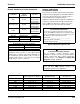
WATER SUPPLY AND DRAIN LINE SIZING/CONNECTIONS
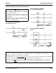
Refer to “Ice Machine Dimensions” at the beginning of Section 2 for the exact locations of inlets and drains for the model you are working on.
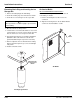
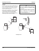
Typical Water Supply Drain Installation
!
Caution
Plumbing must conform to state and local codes.
Location
Water
Temperature
Water Pressure Ice Machine Fitting
Tubing Size Up to Ice Machine
Fitting
Ice Making
Water Inlet
35°F (1.6°C) Min.
90°F (32.2°C) Max.
20 psi (1.4 bar) Min.
80 psi (5.52 bar) Max.
3/8" Female Pipe Thread
1/2” FPT S3300 Only
3/8" (.95 cm) min inside diameter
1/2” (1.27 cm) S3300 Only
Ice Making
Water Drain
--- ---
1/2" Female Pipe Thread
1” FPT S3300 Only
1” FPT Base Drain S3300 Only
1/2" (1.27 cm) min inside diameter
1” (2.54 cm) S3300 Only
Condenser
Water Inlet
90°F (32.2°C) Max.
Standard
20 psi (1.4 bar) Min.
150 psi (10.34 bar) Max.
High Pressure Option
20 psi (1.4 bar) Min.
350 psi (24.1 bar) Max.
3/8" Female Pipe Thread
1” Female Pipe Thread S3300 Only
Condenser
Water Drain
--- ---
1/2" Female Pipe Thread
1” FPT S3300 Only
1/2" (1.27 cm) min inside diameter
1” (2.54 cm) S3300 Only
Bin Drain
--- ---
3/4" Female Pipe Thread 3/4" (1.91 cm) minimum inside
diameter
Large Capacity
Bin Drain
--- ---
1” Male Pipe Thread
1” (2.54 mm) min. inside diameter
ELECTRICAL ENTRANCE
18” (46 CM) VENT TUBE
AIR GAP
1/2” (1.3 CM) MIN
DRAIN ID
1/2” DRAIN CONNECTION
PLASTIC FITTING ON OPPOSITE
SIDE DO NOT APPLY HEAT
OPEN, TRAPPED AND
VENTED DRAIN
DO NOT TRAP DRAIN LINE,
LEAVE AIR GAP BETWEEN
DRAIN TUBE AND DRAIN
3/8” FPT ICE MAKING WATER INLET FITTING,
PLASTIC FITTING ON OPPOSITE SIDE DO NOT
APPLY HEAT
1/2” FPT CONDENSER WATER DRAIN
(WATER COOLED UNITS ONLY)
3/8” FPT CONDENSER WATER INLET
(WATER COOLED UNITS ONLY
1/2” CPVC SOCKET AUXILLARY BASE
DRAIN