S Model Ice Machines Installation, Use & Care Manual This manual is updated as new information and models are released. Visit our website for the latest manual. www.manitowocfsg.
Safety Notices Read These Before Proceeding: As you work on Manitowoc equipment, be sure to pay close attention to the safety notices in this manual. Disregarding the notices may lead to serious injury and/ or damage to the equipment. Throughout this manual, you will see the following types of safety notices: ! Warning Text in a Warning box alerts you to a potential personal injury situation. Be sure to read the Warning statement before proceeding, and work carefully.
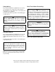
Table of Contents Section 1 General Information Model Numbers . . . . . . . . . . . . . . . . . . . . . . . . . . . . . . . . . . . . . . . . . . . . . . . . . How to Read a Model Number . . . . . . . . . . . . . . . . . . . . . . . . . . . . . . . . . . . . . Ice Cube Sizes . . . . . . . . . . . . . . . . . . . . . . . . . . . . . . . . . . . . . . . . . . . . . . . . . . Accessories . . . . . . . . . . . . . . . . . . . . . . . . . . . . . . . . . . . . . . . . . . . . . . . . . . . . Bin Caster . . . .
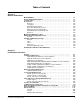
Table of Contents (continued) Electrical Requirements . . . . . . . . . . . . . . . . . . . . . . . . . . . . . . . . . . . . . . . . Ground Fault Circuit Interupter . . . . . . . . . . . . . . . . . . . . . . . . . . . . . . . . . . Minimum Power Cord Specifications . . . . . . . . . . . . . . . . . . . . . . . . . . . . . . Maximum breaker size & Minimum Circuit Amperage Chart . . . . . . . . . . . Self-Contained Electrical Wiring Connections . . . . . . . . . . . . . . . . . . . . . . . .
Table of Contents (continued) Section 3 Ice Machine Operation Component Identification . . . . . . . . . . . . . . . . . . . . . . . . . . . . . . . . . . . . . . . . . S Model Single Evaportor Models . . . . . . . . . . . . . . . . . . . . . . . . . . . . . . . . S Model Multiple Evaporator Models . . . . . . . . . . . . . . . . . . . . . . . . . . . . . Sequence Of Operation . . . . . . . . . . . . . . . . . . . . . . . . . . . . . . . . . . . . . . . . . . .
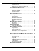
Table of Contents (continued) Section 5 Before Calling For Service Checklist . . . . . . . . . . . . . . . . . . . . . . . . . . . . . . . . . . . . . . . . . . . . . . . . . . . . . . . Safety Limit Feature . . . . . . . . . . . . . . . . . . . . . . . . . . . . . . . . . . . . . . . . . . . . . .
Section 1 General Information Model Numbers ! Warning This manual covers the following models: PERSONAL INJURY POTENTIAL Self-Contained Air-Cooled Self-Contained Water-Cooled Remote SD0302A SY0304A SD0303W SY0305W ------- SD0322A SY0324A SD0323W SY0325W ------- SR0420A SD0422A SY0424A SR0421W SD0423W SY0425W ---------- SD0452A SY0454A SD0453W SY0455W ------- SR0500A SD0502A SY0504A SR0501W SD0503W SY0505W SR0590N SD0592N SY0594N SD0602A SY0604A SD0603W SY0605W SD0692N SY0694N SR0850A
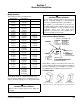
General Information Section 1 Accessories MANITOWOC CLEANER AND SANITIZER Contact your Manitowoc distributor for these optional accessories: Manitowoc Ice Machine Cleaner and Sanitizer are available in convenient 16 oz. (473 ml) bottles. These are the only cleaner and sanitizer approved for use with Manitowoc products. BIN CASTER Replaces standard legs. ICE BAGGER Maximize profits from bagged ice sales with this convenient accessory.
Section 1 General Information Model/Serial Number Location These numbers are required when requesting information from your local Manitowoc distributor, or Manitowoc Foodservice. The model and serial number are listed on the MODEL/ SERIAL NUMBER DECAL affixed to the ice machine, remote condenser and storage bin.
General Information Section 1 Owner Warranty Registration Card GENERAL EXCLUSIONS The packet containing this manual also includes warranty information. Warranty coverage begins the day your new ice machine is installed. The following items are not included in the ice machine’s warranty coverage: Important Complete and mail the OWNER WARRANTY REGISTARATION CARD as soon as possible to validate the installation date.
Section 1 General Information Residential Ice Machine Limited Warranty WHAT DOES THIS LIMITED WARRANTY COVER? Subject to the exclusions and limitations below, Manitowoc Ice, Inc.
General Information Section 1 THIS PAGE INTENTIONALLY LEFT BLANK 1-6 Part Number 000000966 10/09
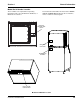
Section 2 Installation Instructions Section 2 Installation Instructions General These instructions are provided to assist the qualified installer. Check your local Yellow Pages for the name of the nearest Manitowoc distributor, or call Manitowoc Foodservice for information regarding start-up services. Important Failure to follow these installation guidelines may affect warranty coverage. Ice Machine Dimensions S320/S420 AIR AND WATER-COOLED ICE MACHINES ELECTRICAL AUCS ELECTRICAL 2.20" (5.58cm) 5.
Installation Instructions Section 2 S600 AIR AND WATER-COOLED ICE MACHINES H 1.50" (3.81cm) ELECTRICAL 8.50" (21.60cm) A AUCS CONNECTIONS 6.50" (16.5cm) B CONDENSER WATER OUTLET 1/2"FPT (Water-Cooled Only) 2.61" (6.62cm) 5.06" (12.85cm) 1.81" 6.68" (16.96cm) (4.59cm) 2.85" (7.30cm) D AUXILLARY BASE DRAIN 1/2"CPVC SOCKET CONDENSER WATER INLET 3/8"FPT (Water-Cooled Only) DRAIN 1/2"NPTF 7.75" (19.7 cm) WATER INLET 3/8"FPT 4.25" (10.81 cm) 17.25" (43.81 cm) W Ice Machine S600 Dimension A 11.
Section 2 Installation Instructions S300/S450/S500/S850/S1000/S1200 AIR AND WATER-COOLED ICE MACHINES ELECTRICAL 2.20" (5.58cm) H A B C E AUCS CONNECTIONS 1.81" (4.59cm) 2.61" (6.62cm) F 4.21" (10.69cm) 2.85" (7.30cm) 5.06" (12.85cm) 1.06 (2.7cm) 6.68" (16.96cm) CONDENSER WATER OUTLET 1/2"FPT (Water-Cooled Only) D AUXILLARY BASE DRAIN 1/2"CPVC SOCKET 8.49" (21.56cm) 25.52" (64.
Installation Instructions Section 2 S500/S850/S1000 REMOTE ICE MACHINES ELECTRICAL REMOTE CONDENSER ELECTRICAL 2.20" (5.58cm) A H B 1.81" (4.59cm) 2.61" (6.62cm) 1.06 (2.69cm) 6.12" (15.54cm) D 5.06" (12.85cm) 6.68" (16.96cm) 12.26" (42.27cm) WATER INLET 3/8"FPT 16.64" (64.82cm) DRAIN 1/2"NPTF W Ice Machine S300 S450 S500 S850 S1000 2-4 Dimension A 14.00 in (35.6 cm) 19.25 in (48.9 cm) 19.25 in (48.9 cm) 23.82 in (60.5 cm) 23.82 in (60.5 cm) Dimension B NA 17.5 in (44.45 cm) 17.
Section 2 Installation Instructions S1400 / S1600 / S1800 AIR AND WATER-COOLED ICE MACHINES 2.50" (6.35cm) ELECTRICAL H A B C 11.0" (27.9cm) AuCS Connections E 2.0" (5.1cm) F WATER INLET 3/8"FPT 5.75" (14.6cm) CONDENSER WATER OUTLET 1/2"FPT (Water-Cooled Only) 1.1" (2.8cm) 4.0" 7.8" (19.8cm) (10.2cm) 10.25" (26.0cm) CONDENSER WATER INLET 1/2"FPT (Water-Cooled Only) D 3.0" (7.6cm) 11.0" (27.9cm) 3.75" (9.
Installation Instructions Section 2 S3300 WATER-COOLED MODEL 48.00 CONDENSER WATER INLET 1"FPT (Water-Cooled Only) 30.00 ELECTRICAL 36.00 7.00 23.00 8.00 32.50 34.00 CONDENSER WATER OUTLET 1"FPT (Water-Cooled Only) 36.00 32.50 29.50 8.25 BASE DRAIN 1"FPT 1.50 24.00 DRAIN 1"FPT WATER INLET 1/2"FPT Remote Condenser Dimensions JC0495/JC0895/JC1395 OPTIONAL 38.0” (96.5 CM) 34.0” (86.4 CM) 29.5” (74.3 CM) 27.9” (71.0 CM) 1.5” (3.6 CM) 29.2” (74.1 CM) 6.0” (15.2 CM) 3.5” (8.
Section 2 Installation Instructions Ice Storage Bin Dimensions 22 INCH (56 CM) ICE STORAGE BINS Bin Model B320 B420 Dimension A 34.0 in (86.3 cm) 34.0 in (86.3 cm) Dimension B 32.0 in (81.3 cm) 44.0 in (111.7 cm) 30 INCH (76 CM) ICE STORAGE BINS Bin Model B170 B400 B570 Dimension A 29.5 in (74.9 cm) 34.0 in (86.3 cm) 34.0 in (86.3 cm) Part Number 000000966 10/09 48 INCH (122 CM) ICE STORAGE BINS B970 Dimension B 19.1 in (48.5 cm) 32.0 in (81.3 cm) 44.0 in (111.
Installation Instructions Section 2 Large Capacity Ice Storage Bin Dimensions 30 INCH (76 CM) ! Warning A 34” (86.4 cm) B All Manitowoc ice machines require the ice storage system (bin, dispenser, etc.) to incorporate an ice deflector. The S600, S850, S1000 ice machines require adding Manitowoc Ice Deflector Kit K00347 when installing with non-Manitowoc ice storage systems.
Section 2 Installation Instructions Location of Ice Machine The location selected for the ice machine must meet the following criteria. If any of these criteria are not met, select another location. • The location must be free of airborne and other contaminants. • The air temperature must be at least 35°F (1.6°C), but must not exceed 110°F (43.4°C).
Installation Instructions Section 2 Removing Drain Plug and Leveling the Ice Storage Bin 1. Remove threaded plug from drain fitting. 2. Screw the leveling legs onto the bottom of the bin. 3. Screw the foot of each leg in as far as possible. ! Caution The legs must be screwed in tightly to prevent them from bending. Air-Cooled Baffle SELF-CONTAINED AIR-COOLED ONLY The air-cooled baffle prevents condenser air from recirculating. To install: 1. Remove the back panel screws next to the condenser. 2.
Section 2 Installation Instructions Electrical Service Important GENERAL Observe correct polarity of incoming line voltage. ! Warning All wiring must conform to local, state and national codes. Incorrect polarity can lead to erratic ice machine operation and a safety issue. This is especially critical on 230 volt / 50 cycle ice machines. Fuse/Circuit Breaker VOLTAGE The maximum allowable voltage variation is ±10% of the rated voltage at ice machine start-up (when the electrical load is highest).
Installation Instructions Section 2 MAXIMUM BREAKER SIZE & MINIMUM CIRCUIT AMPERAGE CHART Important Due to continuous improvements, this information is for reference only. Please refer to the ice machine serial number tag to verify electrical data. Serial tag information overrides information listed on this page.
Section 2 Installation Instructions Self-Contained Electrical Wiring Connections ! Warning These diagrams are not intended to show proper wire routing, wire sizing, disconnects, etc., only the correct wire connections. All electrical work, including wire routing and grounding, must conform to local, state and national electrical codes. Though wire nuts are shown in the drawings, the ice machine field wiring connections may use either wire nuts or screw terminals.
Installation Instructions Section 2 Remote Electrical Wiring Connections REMOTE ICE MACHINE WITH SINGLE CIRCUIT MODEL CONDENSER 208-230/3/60 OR 440-480/3/60 ! Warning These diagrams are not intended to show proper wire routing, wire sizing, disconnects, etc., only the correct wire connections. SINGLE CIRCUIT REMOTE CONDENSER L1 NOTE: FAN MOTOR IS 208-230V L2 All electrical work, including wire routing and grounding, must conform to local, state and national electrical codes.
Section 2 Installation Instructions Water Supply and Drain Requirements DRAIN CONNECTIONS WATER SUPPLY Follow these guidelines when installing drain lines to prevent drain water from flowing back into the ice machine and storage bin: Local water conditions may require treatment of the water to inhibit scale formation, filter sediment, and remove chlorine odor and taste. • Drain lines must have a 1.5 inch drop per 5 feet of run (2.5 cm per meter), and must not create traps.
Installation Instructions Section 2 WATER SUPPLY AND DRAIN LINE SIZING/CONNECTIONS ! Caution Plumbing must conform to state and local codes. Location Water Temperature Water Pressure Ice Machine Fitting Tubing Size Up to Ice Machine Fitting Ice Making Water Inlet 35°F (1.6°C) Min. 90°F (32.2°C) Max. 20 psi (1.4 bar) Min. 80 psi (5.52 bar) Max. 3/8" Female Pipe Thread 1/2” FPT S3300 Only 3/8" (.95 cm) min inside diameter 1/2” (1.
Section 2 Installation Instructions Remote Condenser/Line Set Installation Ice Machine Remote Single Circuit Condenser S500 JC0495 S600/S800/S1000 JC0895 S1400/S1600/ S1800 JC1395 *Line Set RT RL Discharge Line 1/2" (1.27 cm) 1/2" (1.27 cm) Line Set* RT-20-R404A RT-35-R404A RT-50-R404A RT-20-R404A RT-35-R404A RT-50-R404A RL-20-R404A RL-35-R404A RL-50-R404A Liquid Line 5/16" (.79 cm) 3/8" (.
Installation Instructions Section 2 GENERAL Condensers must be mounted horizontally with the fan motor on top with nothing obstructing it. There must be at least a 16” clearance from the bottom for air intake. The front coupling panel & one other panel (back or side) must also be unobstructed. Remote condenser installations consist of vertical and horizontal line sets between the ice machine and the condenser. When combined, they must fit within approved specifications.
Section 2 Installation Instructions Make the following calculations to make sure the line set layout is within specifications. CALCULATING REMOTE CONDENSER INSTALLATION DISTANCES Line Set Length 1. Insert the measured rise into the formula below. Multiply by 1.7 to get the calculated rise. (Example: A condenser located 10 feet above the ice machine has a calculated rise of 17 feet.00) The maximum length is 100' (30.5 m). The ice machine compressor must have the proper oil return.
Installation Instructions Section 2 LENGTHENING OR REDUCING LINE SET LENGTHS REMOTE RECEIVER SERVICE VALVE In most cases, by routing the line set properly, shortening will not be necessary. When shortening or lengthening is required, do so before connecting the line set to the ice machine or the remote condenser. This prevents the loss of refrigerant in the ice machine or condenser. The receiver service valve is closed during shipment. Open the valve prior to starting the ice machine.
Section 2 Installation Instructions Remote Ice Machine Usage with Non-Manitowoc Multi-Circuit Condensers WARRANTY FAN MOTOR The sixty (60) month compressor warranty, including thirty six (36) month labor replacement warranty, shall not apply when the remote ice machine is not installed within the remote specifications. The foregoing warranty shall not apply to any ice machine installed and/or maintained inconsistent with the technical instructions provided by Manitowoc Ice, Inc.
Installation Instructions Section 2 NON-MANITOWOC MULTI-CIRCUIT CONDENSER SIZING CHART Ice Machine Model Refrigerant Type Charge Heat of Rejection Average Btu/hr Peak Btu/hr Internal Condenser Volume (cu ft) Min Design Pressure Max S500 R-404A 6 lbs. 6,100 6,900 0.020 0.035 S600 S850 S1000 S1400 S1600 R404A R-404A R-404A R-404A R-404A 6.5 lbs. 8.5 lbs. 8.5 lbs. 11 lbs. 11.5 lbs 9,000 13,000 17,700 20,700 21,000 13,900 16,000 21,000 24,500 31,000 0.045 0.045 0.045 0.085 0.085 0.060 0.
Section 2 Installation Instructions INSTALLATION CHECK LIST Is the Ice Machine level? Has all of the internal packing been removed? Have all of the electrical and water connections been made? Has the supply voltage been tested and checked against the rating on the nameplate? Is there proper clearance around the ice machine for air circulation? Has the ice machine been installed where ambient temperatures will remain in the range of 35° - 110°F (1.6° - 43.
Installation Instructions Section 2 Before Starting the Ice Machine AuCS® Automatic Cleaning System All Manitowoc ice machines are factory-operated and adjusted before shipment. Normally, new installations do not require any adjustment. This optional accessory monitors ice making cycles and initiates cleaning procedures automatically. The AuCS® accessory can be set to automatically clean or sanitize the ice machine every 2, 4 or 12 weeks.
Section 3 Ice Machine Operation Section 3 Ice Machine Operation Component Identification S MODEL SINGLE EVAPORTOR MODELS Water Distribution Tube Toggle Switch Water Curtain Ice Thickness Probe Dump Valve Bin Switch Water Level Probe Water Pump Water Inlet Location Water Inlet Valve (Located in Refrigeration Compartment) S MODEL MULTIPLE EVAPORATOR MODELS Control Box Evaporators Water Pumps Ice Dampers Water Level Probe Water Trough Part Number 000000966 10/09 3-1
Ice Machine Operation Section 3 Sequence Of Operation NOTE: The toggle switch must be in the ice position and the water curtain/ice dampers must be in place on the evaporator before the ice machine will start. INITIAL START-UP OR START-UP AFTER AUTOMATIC SHUT-OFF 1. Water Purge Before the refrigerant compressor starts, the water pump and water dump solenoid energize to purge the ice machine of old water. This feature ensures that the ice making cycle starts with fresh water.
Section 3 Ice Machine Operation SEQUENCE OF OPERATION CHART SINGLE EVAPORATOR Ice Making Sequence Of Operation Water Pump Harvest Valve(s) Air Compressor(s) Water Inlet Valve Dump Valve Refrigeration Compressor & Condenser Fan Motor Length Of Time START-UP 1 1. Water Purge On On 35 sec. Off 10 sec.On Off On Off 45 Seconds 2. Refrigeration System Start-Up Off On Off On Off On 5 Seconds FREEZE SEQUENCE 3.
Ice Machine Operation Section 3 SAFETY TIMERS WARM WATER RINSE CYCLE The control board has the following non-adjustable safety timers: Single evaporator models only - Closing the back of the evaporator allows ice to build up on the rear of the evaporator and the plastic evaporator frame parts. After 200 freeze/harvest cycles have been completed the control board will initiate a warm water rinse. • The ice machine is locked into the freeze cycle for 6 minutes before a harvest cycle can be initiated.
Section 3 Ice Machine Operation Operational Checks ICE THICKNESS CHECK GENERAL The ice thickness probe is factory-set to maintain the ice bridge thickness at 1/8" (.32 cm). Manitowoc ice machines are factory-operated and adjusted before shipment. Normally, new installations do not require any adjustment.
Ice Machine Operation HARVEST SEQUENCE WATER PURGE The harvest sequence water purge adjustment may be used when the ice machine is hooked up to special water systems, such as a de-ionized water treatment system. ! Warning Section 3 • During the harvest sequence water purge, the water fill valve energizes and de-energizes by time. The water purge must be at the factory setting of 45 seconds for the water fill valve to energize during the last 15 seconds of the water purge.
Section 4 Maintenance Section 4 Maintenance Cleaning and Sanitizing EXTERIOR CLEANING GENERAL Clean the area around the ice machine as often as necessary to maintain cleanliness and efficient operation. Use cleaners designed for use with stainless steel products. You are responsible for maintaining the ice machine in accordance with the instructions in this manual. Maintenance procedures are not covered by the warranty. Clean and sanitize the ice machine every six months for efficient operation.
Maintenance Manitowoc’s Cleaning Technology Manitowoc Ice Machines include technology that allows the initiation and completion of a cleaning cycle at the flip of a switch. This cycle will permit cleaning of all surfaces that come in contact with the water distribution system. Periodic maintenance must be performed that includes sanitizing the bin and adjacent surface areas, which are not contacted by the water distribution system.
Section 4 Maintenance Cleaning / Sanitizing Procedure GENERAL Clean and sanitize the ice machine every six months for efficient operation. If the ice machine requires more frequent cleaning and sanitizing, consult a qualified service company to test the water quality and recommend appropriate water treatment. The ice machine must be taken apart for cleaning and sanitizing.
Maintenance Section 4 PARTS REMOVAL FOR CLEANING/SANITIZING Single Evaporator Ice Machines A. Remove the water curtain C. Remove the water trough • Gently flex the curtain in the center and remove it from the right side. • Depress tabs on right and left side of the water trough. • Slide the left pin out. • Allow front of water trough to drop as you pull forward to disengage the rear pins. B. Remove the ice thickness probe • Compress the hinge pin on the top of the ice thickness probe.
Section 4 Maintenance Multiple Evaporator Ice Machines A. Remove Splash Shields. C. Remove the water trough shield. • Grasp the top center of splash shields. • • Lift up and then out. Grasp the water trough shield in the center and the left end. • Flex the water trough shield in the center and pull the left end forward until clear of the side wall. Repeat for the right end. • Pull water trough shield forward to remove. B. Remove ice thickness probe.
Maintenance Section 4 Step 7 Mix a solution of cleaner and warm water. Depending upon the amount of mineral buildup, a larger quantity of solution may be required. Use the ratio in the table below to mix enough solution to thoroughly clean all parts. Solution Type Cleaner Water 1 gal. (4 l) Mixed With 16 oz (500 ml) cleaner Step 8 Use 1/2 of the cleaner/water mixture to clean all components.
Section 4 Maintenance Procedure to Clean Heavily Scaled Ice Machines Ice machines that are heavily scaled or have not been cleaned on a regular basis will need to run this procedure. GENERAL Clean and sanitize the ice machine every six months for efficient operation. If the ice machine requires more frequent cleaning and sanitizing, consult a qualified service company to test the water quality and recommend appropriate water treatment. The ice machine must be taken apart for cleaning and sanitizing.
Maintenance Section 4 PARTS REMOVAL FOR CLEANING/SANITIZING Single Evaporator Ice Machines A. Remove the water curtain D. Remove the water level probe • Gently flex the curtain in the center and remove it from the right side. • Pull the water level probe straight down to disengage. • Slide the left pin out. • Lower the water level probe until the wiring connector is visible. B. Remove the ice thickness probe • Compress the hinge pin on the top of the ice thickness probe.
Section 4 Maintenance B. A. G. E. F. D.
Maintenance Section 4 Multiple Evaporator Ice Machines A. Remove panels G. • Grasp ice damper and apply pressure toward the back mounting bracket. • Remove both front panels • Remove top panel • Apply pressure to the front mounting bracket with thumb. B. Remove front evaporator shield. • Remove four quarter turn connectors • Pull ice damper downward when the front ice damper pin disengages. • Remove splash shield C. Remove left and right evaporator top covers.
Section 4 Maintenance A C D I F G E B H A Part Number 000000966 10/09 4-11
Maintenance Section 4 Step 7 Mix a solution of cleaner and warm water. Depending upon the amount of mineral buildup, a larger quantity of solution may be required. Use the ratio in the table below to mix enough solution to thoroughly clean all parts. Solution Type Cleaner Water 1 gal. (4 l) Mixed With 16 oz (500 ml) cleaner Step 8 Use 1/2 of the cleaner/water mixture to clean all components.
Section 4 Maintenance Step 16 The ice machine will stop after the sanitize cycle (approximately *35 minutes). Place the toggle switch in the OFF position and disconnect power to the ice machine. *S3300 Only - 80 minutes. ! Warning Disconnect the electric power to the ice machine at the electric service switch box.. Step 17 Refer to step 6 and disassemble components. After dissembling proceed to step 18. Step 18 Mix a solution of sanitizer and warm water. Solution Type Sanitizer Water 6 gal.
Maintenance Section 4 Additional Component Removal Water Inlet Valve The following components may be removed for easier access in some installations or they may need to be removed and cleaned to correct an operational problem. The water inlet valve normally does not require removal for cleaning. Refer to Section 5 for a list of causes for “No Water Entering Water Trough” or “Water Overflows Water Trough. Door Removal 1.
Section 4 Maintenance Water Dump Valve The water dump valve normally does not require removal for cleaning. To determine if removal is necessary: COIL SPRING 1. Set the toggle switch to ICE. 2. Verify the water trough fills with water at the beginning of the freeze cycle. 3. While the ice machine is in the freeze mode, check the water trough to determine if the dump valve is leaking. If there is no or little water in the water trough (during the freeze cycle) the dump valve is leaking.
Maintenance Section 4 Ice Machine Inspection Cleaning the Condenser Check all water fittings and lines for leaks. Also, make sure the refrigeration tubing is not rubbing or vibrating against other tubing, panels, etc. GENERAL Do not put anything (boxes, etc.) on the sides or back of the ice machine. There must be adequate airflow through and around the ice machine to maximize ice production and ensure long component life.
Section 4 Maintenance 4. Straighten any bent condenser fins with a fin comb. “COMB” DOWN ONLY Water-Cooled Condenser and Water Regulating Valve Symptoms of restrictions in the condenser water circuit include: • Low ice production • High water consumption • High operating temperatures • High operating pressures CONDENSER If the ice machine is experiencing any of these symptoms, the water-cooled condenser and water regulating valve may require cleaning due to scale build-up.
Maintenance Section 4 Guardian Slime is a leading cause of ice machine breakdowns and biological growth is a health concern. The Guardian system releases chlorine dioxide on a controlled basis to inhibit the growth of bacteria and fungi that form slime and cause malodors in the food zone of ice machines. SACHET INSTALLATION/REPLACEMENT PROCEDURE 1. Loosen the left screw and open the left front door. The right front panel does not need to be removed.
Section 4 Maintenance Removal from Service/Winterization GENERAL Special precautions must be taken if the ice machine is to be removed from service for an extended period of time or exposed to ambient temperatures of 32°F (0°C) or below. ! Caution WATER-COOLED ICE MACHINES 1. Perform steps 1-6 under “Self-Contained Air-Cooled Ice Machines.” 2. Disconnect the incoming water and drain lines from the water-cooled condenser. 3.
Maintenance Section 4 THIS PAGE INTENTIONALLY LEFT BLANK 4-20 Part Number 000000966 10/09
Section 5 Before Calling For Service Section 5 Before Calling For Service Checklist If a problem arises during operation of your ice machine, follow the checklist below before calling service. Routine adjustments and maintenance procedures are not covered by the warranty. Problem Ice machine does not operate. Ice machine stops, and can be restarted by moving the toggle switch to OFF and back to ICE. Ice machine does not release ice or is slow to harvest. Ice machine does not cycle into harvest mode.
Before Calling For Service Problem Ice machine produces shallow or incomplete cubes, or the ice fill pattern on the evaporator is incomplete. Low ice capacity. Section 5 Possible Cause Ice thickness probe is out of adjustment. To Correct Adjust the ice thickness probe. (See Section 4) Water trough level is too low. Check the water level probe for damage. (See Section 3) Water inlet valve filter screen is dirty. Remove the water inlet valve and clean the filter screen.
Section 5 Before Calling For Service THIS PAGE INTENTIONALLY LEFT BLANK Part Number 000000966 10/09 5-3
Before Calling For Service Section 5 THIS PAGE INTENTIONALLY LEFT BLANK 5-4 Part Number 000000966 10/09
© 2008 Manitowoc Continuing product improvements may necessitate change of specifications without notice. Part Number 000000966 10/09 Manitowoc Foodservice 2110 South 26th Street, P.O. Box 1720 Manitowoc, WI 54221-1720, USA Ph: 920-682-0161 Fax: 920-683-7589 Visit us online at: www.manitowocfsg.