S Model Ice Machines Installation Use and Care Manual Thank you for selecting a Manitowoc Ice Machine, the dependability leader in ice making equipment and related products. With proper installation, care and maintenance, your new Manitowoc Ice Machine will provide you with many years of reliable and economical performance. This manual is updated as new information and models are released. Visit our website for the latest manual. www.manitowocice.
Safety Notices Procedural Notices As you work on an S Model Series Ice Machine, be sure to pay close attention to the safety notices in this manual. Disregarding the notices may lead to serious injury and/or damage to the ice machine. As you work on an S Model Series Ice Machine, be sure to read the procedural notices in this manual. These notices supply helpful information which may assist you as you work.
Table of Contents Section 1 General Information Model Numbers . . . . . . . . . . . . . . . . . . . . . . . . . . . . . . . . . . . . . . . . . . . . . . . . . How to Read a Model Number . . . . . . . . . . . . . . . . . . . . . . . . . . . . . . . . . . . . . Ice Cube Sizes . . . . . . . . . . . . . . . . . . . . . . . . . . . . . . . . . . . . . . . . . . . . . . . . . . Accessories . . . . . . . . . . . . . . . . . . . . . . . . . . . . . . . . . . . . . . . . . . . . . . . . . . . . Bin Caster . . . .
Table of Contents (continued) Self-Contained Electrical Wiring Connections . . . . . . . . . . . . . . . . . . . . . . . . Self Contained Ice Machine 115/1/60 or 208-230/1/60 . . . . . . . . . . . . . . . . Self Contained Ice Machine 208-230/3/60 . . . . . . . . . . . . . . . . . . . . . . . . . . Self Contained Ice Machine 230/1/50 . . . . . . . . . . . . . . . . . . . . . . . . . . . . . For United Kingdom Only . . . . . . . . . . . . . . . . . . . . . . . . . . . . . . . . . . . . . . . . .
Table of Contents (continued) Section 4 Maintenance General . . . . . . . . . . . . . . . . . . . . . . . . . . . . . . . . . . . . . . . . . . . . . . . . . . . . . . . . Ice Machine Inspection . . . . . . . . . . . . . . . . . . . . . . . . . . . . . . . . . . . . . . . . . . . Exterior Cleaning . . . . . . . . . . . . . . . . . . . . . . . . . . . . . . . . . . . . . . . . . . . . . . . . Cleaning the Condenser . . . . . . . . . . . . . . . . . . . . . . . . . . . . . . . . . . . . . . . . . . General .
Table of Contents (continued) 4 Part Number 000000345
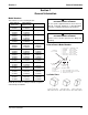
Section 1 General Information Section 1 General Information Model Numbers ! Warning This manual covers the following models: Self-Contained Air-Cooled SD0302A SY0304A SD0322A SY0324A SR0420A SD0422A SY0424A SD0452A SY0454A SR0500A SD0502A SY0504A SD0602A SY0604A SR0850A SD0852A SY0854A SD1002A SY1004A SD1202A SY1204A SD1402A SY1404A SR1600A SD1602A SY1604A SR1800A SD1802A SY1804A Self-Contained Water-Cooled SD0303W SY0305W SD0323W SY0325W SR0421W SD0423W SY0425W SD0453W SY0455W SR0501W SD0503W SY0505W S
General Information Section 1 Accessories MANITOWOC CLEANER AND SANITIZER Contact your Manitowoc distributor for these optional accessories: Manitowoc Ice Machine Cleaner and Sanitizer are available in convenient 16 oz. (473 ml) bottles. These are the only cleaner and sanitizer approved for use with Manitowoc products. BIN CASTER Replaces standard legs. ICE BAGGER Maximize profits from bagged ice sales with this convenient accessory.
Section 1 General Information Model/Serial Number Location These numbers are required when requesting information from your local Manitowoc distributor, or Manitowoc Ice, Inc. The model and serial number are listed on the MODEL/ SERIAL NUMBER DECAL affixed to the ice machine, remote condenser and storage bin.
General Information Section 1 Owner Warranty Registration Card GENERAL EXCLUSIONS The packet containing this manual also includes warranty information. Warranty coverage begins the day your new ice machine is installed. The following items are not included in the ice machine’s warranty coverage: Important Complete and mail the OWNER WARRANTY REGISTARATION CARD as soon as possible to validate the installation date.
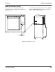
Section 2 Installation Instructions Section 2 Installation Instructions General These instructions are provided to assist the qualified installer. Check your local Yellow Pages for the name of the nearest Manitowoc distributor, or call Manitowoc Ice, Inc. for information regarding start-up services. Important Failure to follow these installation guidelines may affect warranty coverage. Ice Machine Dimensions S320/S420 AIR AND WATER-COOLED ICE MACHINES ELECTRICAL AUCS ELECTRICAL 2.20" (5.58cm) 5.
Installation Instructions Section 2 S600 AIR AND WATER-COOLED ICE MACHINES H 1.50" (3.81cm) ELECTRICAL 8.50" (21.60cm) A AUCS CONNECTIONS 6.50" (16.5cm) B CONDENSER WATER OUTLET 1/2"FPT (Water-Cooled Only) 2.61" (6.62cm) 5.06" (12.85cm) 1.81" 6.68" (16.96cm) (4.59cm) 2.85" (7.30cm) D AUXILLARY BASE DRAIN 1/2"CPVC SOCKET CONDENSER WATER INLET 3/8"FPT (Water-Cooled Only) DRAIN 1/2"NPTF 7.75" (19.7 cm) WATER INLET 3/8"FPT 4.25" (10.81 cm) 17.25" (43.81 cm) W Ice Machine S600 Dimension A 11.
Section 2 Installation Instructions S300/S450/S500/S850/S1000/S1200 AIR AND WATER-COOLED ICE MACHINES ELECTRICAL 2.20" (5.58cm) H A B C E AUCS CONNECTIONS 1.81" (4.59cm) 2.61" (6.62cm) F 4.21" (10.69cm) 2.85" (7.30cm) 5.06" (12.85cm) 1.06 (2.7cm) 6.68" (16.96cm) CONDENSER WATER OUTLET 1/2"FPT (Water-Cooled Only) D AUXILLARY BASE DRAIN 1/2"CPVC SOCKET 8.49" (21.56cm) 25.52" (64.
Installation Instructions Section 2 S500/S850/S1000 REMOTE ICE MACHINES ELECTRICAL REMOTE CONDENSER ELECTRICAL 2.20" (5.58cm) A H B 1.81" (4.59cm) 2.61" (6.62cm) 1.06 (2.69cm) 6.12" (15.54cm) D 5.06" (12.85cm) 6.68" (16.96cm) 12.26" (42.27cm) WATER INLET 3/8"FPT 16.64" (64.82cm) DRAIN 1/2"NPTF SV3146 Ice Machine S300 S450 S500 S850 S1000 2-4 W Dimension A 14.00 in (35.6 cm) 19.25 in (48.9 cm) 19.25 in (48.9 cm) 23.82 in (60.5 cm) 23.82 in (60.5 cm) Dimension B NA 17.5 in (44.
Section 2 Installation Instructions S1400 / S1600 / S1800 AIR AND WATER-COOLED ICE MACHINES 2.50" (6.35cm) ELECTRICAL H A B C 11.0" (27.9cm) AuCS Connections E 2.0" (5.1cm) F WATER INLET 3/8"FPT 5.75" (14.6cm) CONDENSER WATER OUTLET 1/2"FPT (Water-Cooled Only) 1.1" (2.8cm) 4.0" 7.8" (19.8cm) (10.2cm) 10.25" (26.0cm) CONDENSER WATER INLET 1/2"FPT (Water-Cooled Only) D 3.0" (7.6cm) 11.0" (27.9cm) 3.75" (9.
Installation Instructions Section 2 Ice Storage Bin Dimensions 22 INCH (56 CM) ICE STORAGE BINS 48 INCH (130 CM) ICE STORAGE BINS SV1614 SV1297 Bin Model B320 B420 Dimension A 34.0 in (86.3 cm) 34.0 in (86.3 cm) Dimension B 32.0 in (81.3 cm) 44.0 in (111.7 cm) 30 INCH (76 CM) ICE STORAGE BINS B970 SV1609 Bin Model B170 B400 B570 2-6 Dimension A 29.5 in (74.9 cm) 34.0 in (86.3 cm) 34.0 in (86.3 cm) Dimension B 19.1 in (48.5 cm) 32.0 in (81.3 cm) 44.0 in (111.
Section 2 Installation Instructions Large Capacity Ice Storage Bin Dimensions 30 INCH (76 CM) ! Warning A 34” (86.4 cm) B All Manitowoc ice machines require the ice storage system (bin, dispenser, etc.) to incorporate an ice deflector. The S600, S850, S1000 ice machines require adding Manitowoc Ice Deflector Kit K00347 when installing with non-Manitowoc ice storage systems.
Installation Instructions Section 2 Remote Condenser Dimensions JC0495/JC0895/JC1395 SV1297 2-8 Part Number 000000345
Section 2 Installation Instructions Location of Ice Machine Ice Machine Heat of Rejection The location selected for the ice machine must meet the following criteria. If any of these criteria are not met, select another location. • The location must be free of airborne and other contaminants. • The air temperature must be at least 35°F (1.6°C), but must not exceed 110°F (43.4°C).
Installation Instructions Section 2 Removing Drain Plug and Leveling the Ice Storage Bin 1. Remove threaded plug from drain fitting. 2. Screw the leveling legs onto the bottom of the bin. 3. Screw the foot of each leg in as far as possible. ! Caution The legs must be screwed in tightly to prevent them from bending. Air-Cooled Baffle SELF-CONTAINED AIR-COOLED ONLY The air-cooled baffle prevents condenser air from recirculating. To install: 1. Remove the back panel screws next to the condenser. 2.
Section 2 Installation Instructions Electrical Service Important GENERAL Observe correct polarity of incoming line voltage. ! Warning All wiring must conform to local, state and national codes. Incorrect polarity can lead to erratic ice machine operation and a safety issue. This is especially critical on 230 volt / 50 cycle ice machines. Fuse/Circuit Breaker VOLTAGE The maximum allowable voltage variation is ±10% of the rated voltage at ice machine start-up (when the electrical load is highest).
Installation Instructions Section 2 MAXIMUM BREAKER SIZE & MINIMUM CIRCUIT AMPERAGE CHART (* indicates preliminary data) Ice Machine S300 S320 S420/S450 S500 S600 S850 S1000 S1200 S1400 S1600 S1800 Voltage Phase Cycle 115/1/60 230/1/50 115/1/60 208-230/1/60 230/1/50 115/1/60 208-230/1/60 230/1/50 115/1/60 208-230/1/60 230/1/50 208-230/1/60 230/1/50 208-230/1/60 208-230/3/60 230/1/50 208-230/1/60 208-230/3/60 230/1/50 208-230/1/60 208-230/3/60 230/1/50 208-230/1/60 208-230/3/60 230/1/50 208-23
Section 2 Installation Instructions Self-Contained Electrical Wiring Connections ! Warning These diagrams are not intended to show proper wire routing, wire sizing, disconnects, etc., only the correct wire connections. SELF CONTAINED ICE MACHINE 208-230/3/60 All electrical work, including wire routing and grounding, must conform to local, state and national electrical codes. Though wire nuts are shown in the drawings, the ice machine field wiring connections may use either wire nuts or screw terminals.
Installation Instructions Section 2 Remote Electrical Wiring Connections REMOTE ICE MACHINE WITH SINGLE CIRCUIT MODEL CONDENSER 208-230/3/60 OR 380-415/3/50 ! Warning These diagrams are not intended to show proper wire routing, wire sizing, disconnects, etc., only the correct wire connections. SINGLE CIRCUIT REMOTE CONDENSER L1 NOTE: FAN MOTOR IS 208-230V L2 All electrical work, including wire routing and grounding, must conform to local, state and national electrical codes.
Section 2 Installation Instructions Water Supply and Drain Requirements DRAIN CONNECTIONS WATER SUPPLY Follow these guidelines when installing drain lines to prevent drain water from flowing back into the ice machine and storage bin: Local water conditions may require treatment of the water to inhibit scale formation, filter sediment, and remove chlorine odor and taste.
Installation Instructions Section 2 WATER SUPPLY AND DRAIN LINE SIZING/CONNECTIONS ! Caution Plumbing must conform to state and local codes. Location Water Temperature Water Pressure Ice Machine Fitting Ice Making Water Inlet 35°F (1.6°C) Min. 90°F (32.2°C) Max. 20 psi (137.9 kPA) Min. 80 psi (551.5 kPA) Max. 3/8" Female Pipe Thread Tubing Size Up to Ice Machine Fitting 3/8" (.95 cm) minimum inside diameter Ice Making Water Drain --- --- 1/2" Female Pipe Thread 1/2" (1.
Section 2 Installation Instructions Remote Condenser/Line Set Installation Ice Machine Remote Single Circuit Condenser S500 JC0495 S600/S800/S1000 JC0895 S1400/S1600/ S1800 *Line Set RT RL JC1395 Discharge Line 1/2" (1.27 cm) 1/2" (1.27 cm) Line Set* RT-20-R404A RT-35-R404A RT-50-R404A RT-20-R404A RT-35-R404A RT-50-R404A RL-20-R404A RL-35-R404A RL-50-R404A Liquid Line 5/16" (.79 cm) 3/8" (.95 cm) IMPORTANT EPA CERTIFIED TECHNICIANS If remote line set length is between 50' and 100' (15.2530.
Installation Instructions Section 2 GENERAL GUIDELINES FOR ROUTING LINE SETS Condensers must be mounted horizontally with the fan motor on top. First, cut a 2.5" (6.35 cm) circular hole in the wall or roof for tubing routing. The line set end with the 90° bend will connect to the ice machine. The straight end will connect to the remote condenser. Remote condenser installations consist of vertical and horizontal line sets between the ice machine and the condenser.
Section 2 Installation Instructions Make the following calculations to make sure the line set layout is within specifications. CALCULATING REMOTE CONDENSER INSTALLATION DISTANCES Line Set Length 1. Insert the measured rise into the formula below. Multiply by 1.7 to get the calculated rise. (Example: A condenser located 10 feet above the ice machine has a calculated rise of 17 feet.) The maximum length is 100' (30.5 m). The ice machine compressor must have the proper oil return.
Installation Instructions Section 2 LENGTHENING OR REDUCING LINE SET LENGTHS REMOTE RECEIVER SERVICE VALVE In most cases, by routing the line set properly, shortening will not be necessary. When shortening or lengthening is required, do so before connecting the line set to the ice machine or the remote condenser. This prevents the loss of refrigerant in the ice machine or condenser. The receiver service valve is closed during shipment. Open the valve prior to starting the ice machine.
Section 2 Installation Instructions Remote Ice Machine Usage with Non-Manitowoc Multi-Circuit Condensers WARRANTY FAN MOTOR The sixty (60) month compressor warranty, including thirty six (36) month labor replacement warranty, shall not apply when the remote ice machine is not installed within the remote specifications. The foregoing warranty shall not apply to any ice machine installed and/or maintained inconsistent with the technical instructions provided by Manitowoc Ice, Inc.
Installation Instructions Section 2 NON-MANITOWOC MULTI-CIRCUIT CONDENSER SIZING CHART Ice Machine Model Refrigerant Type Charge Heat of Rejection Average Btu/hr Peak Btu/hr Internal Condenser Volume (cu ft) Min Design Pressure Max S500 R-404A 6 lbs. 7,000 9,600 0.020 0.035 S600 S850 S1000 S1400 S1600 R404A R-404A R-404A R-404A R-404A 6.5 lbs. 8.5 lbs. 8.5 lbs. 11 lbs. 11.5 lbs 9,000 12,000 16,000 19,000 21,000 13,900 18,000 22,000 28,000 31,000 0.045 0.045 0.045 0.085 0.085 0.060 0.
Section 2 Installation Instructions Installation Check List F F F F F F F F F F Is the Ice Machine level? Has all of the internal packing been removed? Have all of the electrical and water connections been made? F F F Has the supply voltage been tested and checked against the rating on the nameplate? F Is there proper clearance around the ice machine for air circulation? F Is the ice machine grounded and polarity correct? Has the ice machine been installed where ambient temperatures will remain in
Installation Instructions Section 2 Before Starting the Ice Machine AuCS® Automatic Cleaning System All Manitowoc ice machines are factory-operated and adjusted before shipment. Normally, new installations do not require any adjustment. This optional accessory monitors ice making cycles and initiates cleaning procedures automatically. The AuCS® accessory can be set to automatically clean or sanitize the ice machine every 2, 4 or 12 weeks.
Section 3 Ice Machine Operation Section 3 Ice Machine Operation Component Identification Water Distribution Tube Toggle Switch Water Curtain Dump Valve Check Valve sv3149 Ice Thickness Probe Bin Switch Water Level Probe Water Pump Water Inlet Location Water Inlet Valve (Located in Refrigeration Compartment) sv3150 Part Number 000000345 3-1
Ice Machine Operation Section 3 Sequence Of Operation NOTE: The toggle switch must be in the ice position and the water curtain must be in place on the evaporator before the ice machine will start. INITIAL START-UP OR START-UP AFTER AUTOMATIC SHUT-OFF 1. Water Purge Before the compressor starts, the water pump and water dump solenoid are energized for 45 seconds, to completely purge the ice machine of old water. This feature ensures that the ice making cycle starts with fresh water.
Section 3 Ice Machine Operation HARVEST SEQUENCE SAFETY TIMERS 5. Water Purge The control board has the following non-adjustable safety timers: The harvest valve(s) opens at the beginning of the water purge to divert hot refrigerant gas into the evaporator. The water pump continues to run, and the water dump valve energizes for 45 seconds to purge the water in the sump trough. The water fill valve energizes (turns on) and de-energizes (turns off) strictly by time.
Ice Machine Operation Section 3 Operational Checks ICE THICKNESS CHECK GENERAL The ice thickness probe is factory-set to maintain the ice bridge thickness at 1/8" (.32 cm). Manitowoc ice machines are factory-operated and adjusted before shipment. Normally, new installations do not require any adjustment.
Section 3 Ice Machine Operation HARVEST SEQUENCE WATER PURGE The harvest sequence water purge adjustment may be used when the ice machine is hooked up to special water systems, such as a de-ionized water treatment system. ! Warning • During the harvest sequence water purge, the water fill valve energizes and de-energizes by time. The water purge must be at the factory setting of 45 seconds for the water fill valve to energize during the last 15 seconds of the water purge.
Ice Machine Operation Section 3 THIS PAGE INTENTIONALLY LEFT BLANK 3-6 Part Number 000000345
Section 4 Maintenance Section 4 Maintenance General Cleaning the Condenser You are responsible for maintaining the ice machine in accordance with the instructions in this manual. Maintenance procedures are not covered by the warranty. GENERAL ! Warning If you do not understand the procedures or the safety precautions that must be followed, call your local Manitowoc service representative to perform the maintenance procedures for you.
Maintenance Section 4 4. Straighten any bent condenser fins with a fin comb. “COMB” DOWN ONLY Water-Cooled Condenser and Water Regulating Valve Symptoms of restrictions in the condenser water circuit include: • Low ice production • High water consumption • High operating temperatures • High operating pressures CONDENSER If the ice machine is experiencing any of these symptoms, the water-cooled condenser and water regulating valve may require cleaning due to scale build-up.
Section 4 Maintenance Guardianf Slime is a leading cause of ice machine breakdowns and biological growth is a health concern. The Guardianf system releases chlorine dioxide on a controlled basis to inhibit the growth of bacteria and fungi that form slime and cause malodors in the food zone of ice machines. SACHET INSTALLATION/REPLACEMENT PROCEDURE 1. Loosen the left screw and open the left front door. The right front panel does not need to be removed.
Maintenance Section 4 Interior Cleaning and Sanitizing ! Caution GENERAL Clean and sanitize the ice machine every six months for efficient operation. If the ice machine requires more frequent cleaning and sanitizing, consult a qualified service company to test the water quality and recommend appropriate water treatment. An extremely dirty ice machine must be taken apart for cleaning and sanitizing.
Section 4 Maintenance SANITIZING PROCEDURE Use sanitizer to remove algae or slime. Do not use it to remove lime scale or other mineral deposits. Step 1 Set the toggle switch to the OFF position after ice falls from the evaporator at the end of a Harvest cycle. Or, set the switch to the OFF position and allow the ice to melt off the evaporator. Step 5 Use the sanitizing solution and a sponge or cloth to sanitize (wipe) all parts and interior surfaces of the ice machine. Sanitize the following areas: A.
Maintenance Section 4 REMOVAL OF PARTS FOR CLEANING/SANITIZING 1. Turn off the electrical and water supply to the ice machine (and dispenser when applicable). 5. Use a soft-bristle brush or sponge (NOT a wire brush) to carefully clean the parts. ! Caution ! Warning Disconnect electric power to the ice machine (and dispenser if applicable) at the electric switch box before proceeding. ! Caution 2. Remove all ice from the bin. 3. Remove the water curtain and the components you want to clean or sanitize.
Section 4 Maintenance Water Curtain Removing the Front Panels NOTE: The front panels do not normally have to be removed. If needed perform the following procedure. 1. Loosen screws. Do not remove they are retained by o-rings to prevent loss. 2. 30 Inch and 48 Inch Models Only: To remove right front door lift up and remove (22 inch machines have a single door, proceed to step 3). A. Gently flex the curtain in the center and remove it from the right side. B. Slide the left pin out.
Maintenance Section 4 Water Distribution Tube Ice Thickness Probe A. Compress the hinge pin on the top of the ice thickness probe. COMPRESS HINGE PIN TO REMOVE ! Warning Removing the distribution tube while the water pump is running will allow water to spray from ice machine. Disconnect the electrical power to the ice machine and dispenser at the electric service switch box and turn off the water supply. NOTE: Distribution tube thumbscrews are retained by orings to prevent loss.
Section 4 Maintenance Water Level Probe Water Trough A. Depress tabs on right and left side of the water trough. B. Allow front of water trough to drop as you pull forward to disengage the rear pins. 1. Remove the water trough. ! Warning Disconnect the electrical power to the ice machine at the electrical disconnect before proceeding. 2. The water level probe normally does not require removal for cleaning. The probe can be wiped and cleaned in place or proceed to step 3. 3.
Maintenance Section 4 Evaporator Tray Removal Water Pump 1. Remove the water trough. ! Warning Disconnect the electric power to the ice machine at the electric service switch box and turn off the water supply before proceeding. 2. Remove thumbscrew on left side of tray. 3. Allow left side of tray to drop as you pull the tray to the left side. Continue until the outlet tube disengages from the right side. 1. Empty the water trough. A. Move the toggle switch from OFF to ICE. B. Wait 45 seconds. C.
Section 4 Maintenance Drain Line Check Valve Water Inlet Valve The drain line check valve normally does not require removal for cleaning. Water loss from the sump trough will indicate removal and cleaning are required. The water inlet valve normally does not require removal for cleaning. Refer to Section 5 for a list of causes for “No Water Entering Water Trough” or “Water Overflows Water Trough. 1. When the ice machine is off, the water inlet valve must completely stop water flow into the machine.
Maintenance Section 4 Water Dump Valve The water dump valve normally does not require removal for cleaning. To determine if removal is necessary: 1. Locate the water dump valve. 2. Set the toggle switch to ICE. 3. While the ice machine is in the freeze mode, check the water trough to determine if the dump valve is leaking. If there is no or little water in the water trough (during the freeze cycle) the dump valve is leaking.
Section 4 Maintenance Removal from Service/Winterization GENERAL Special precautions must be taken if the ice machine is to be removed from service for an extended period of time or exposed to ambient temperatures of 32°F (0°C) or below. ! Caution WATER-COOLED ICE MACHINES 1. Perform steps 1-6 under “Self-Contained Air-Cooled Ice Machines.” 2. Disconnect the incoming water and drain lines from the water-cooled condenser. 3.
Maintenance Section 4 THIS PAGE INTENTIONALLY LEFT BLANK 4-14 Part Number 000000345
Section 5 Before Calling For Service Section 5 Before Calling For Service Checklist If a problem arises during operation of your ice machine, follow the checklist below before calling service. Routine adjustments and maintenance procedures are not covered by the warranty. Problem Ice machine does not operate. Ice machine stops, and can be restarted by moving the toggle switch to OFF and back to ICE. Ice machine does not release ice or is slow to harvest. Ice machine does not cycle into harvest mode.
Before Calling For Service Problem Ice machine produces shallow or incomplete cubes, or the ice fill pattern on the evaporator is incomplete. Low ice capacity. Section 5 Possible Cause Ice thickness probe is out of adjustment. To Correct Adjust the ice thickness probe. (See Section 4) Water trough level is too low. Check the water level probe for damage. (See Section 3) Water inlet valve filter screen is dirty. Remove the water inlet valve and clean the filter screen.
Section 5 Before Calling For Service THIS PAGE INTENTIONALLY LEFT BLANK Part Number 000000345 5-3
Before Calling For Service Section 5 THIS PAGE INTENTIONALLY LEFT BLANK 5-4 Part Number 000000345
MANITOWOC ICE, INC. 2110 South 26th Street P.O. Box 1720 Manitowoc, WI 54221-1720 Phone: (920) 682-0161 Service Fax: (920) 683-7585 Web Site - www.manitowocice.com © 2006 Manitowoc Ice, Inc.