
Service Manual

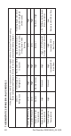
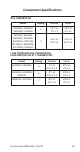
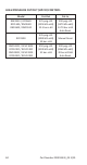
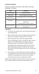
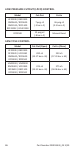
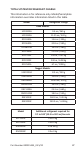


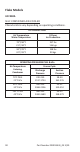
Table Of Contents
- General Information
- Model Numbers
- Installation
- Maintenance
- Sequence of Operation
- Troubleshooting
- Component Specifications
- Charts
- Diagrams
- Wiring Diagrams
- Flake Models
- Nugget Models
- Condensing Units
- Compressor Start Component Wiring
- Refrigeration Tubing Schematics
- UFF0200/UFF0350/UNF0200/UNF0300
- RFF0320/RNF0320 Air-cooled
- RFF0620/RNF0620/RNF1100 Air & Water-cooled
- RNF1020C QuietQube Head Section & RCUF1000 Condensing Unit
- RFF1220C & RCUF1000 Condensing Unit
- RNF2000C QuietQube Head Section & RCUF2200 Condensing Unit
- RFF2200C QuietQube Head Section & RCUF2200 Condensing Unit
- RFF1300 Air & Water-cooled
- RFF2500 Air-cooled

Part Number 000015433_03 5/20 89
Ice Production & Refrigerant Pressure
These charts are used as guidelines to verify correct ice
machine operation.
Accurate collection of data is essential to obtain the
correct diagnosis.
• Zero out manifold gauge set before obtaining pressure
readings to avoid mis-diagnosis.
• Discharge and suction pressure are highest at the
beginning of the cycle. Allow system to stabilize for a
minimum of 10 minutes, then verify the pressures are
within the range indicated.
• Water temperature will affect suction and discharge
pressure - 50°F (10°C) water temperature will result
in pressures on the lower end of the ranges specified.
90°F (32°C) water temperatures will result in pressures
on the upper end of the range specified.
Charts