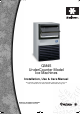
0Front.fm Page 1 Thursday, July 17, 2008 3:41 PM QM45 UnderCounter Model Ice Machines Installation, Use & Care Manual This manual is updated as new information and models are released. Visit our website for the latest manual. www.manitowocfsg.
0Front.fm Page 2 Thursday, July 17, 2008 3:41 PM Safety Notices Read These Before Proceeding: As you work on Manitowoc equipment, be sure to pay close attention to the safety notices in this manual. Disregarding the notices may lead to serious injury and/ or damage to the equipment. Throughout this manual, you will see the following types of safety notices: ! Warning Text in a Warning box alerts you to a potential personal injury situation.
Table of Contents Section 1 General Information Model Numbers. . . . . . . . . . . . . . . . . . . . . . . . . . . . . . . . . . . . . . . . . . . . . . . . . . . 1-1 Accessories. . . . . . . . . . . . . . . . . . . . . . . . . . . . . . . . . . . . . . . . . . . . . . . . . . . . . . 1-1 Tri-liminator Water Filter System . . . . . . . . . . . . . . . . . . . . . . . . . . . . . . . . 1-1 Manitowoc Cleaner and Sanitizer . . . . . . . . . . . . . . . . . . . . . . . . . . . . . . . .
Table of Contents (continued) Energized Parts Chart . . . . . . . . . . . . . . . . . . . . . . . . . . . . . . . . . . . . . . . . . . . . . . 3-3 Operational Checks. . . . . . . . . . . . . . . . . . . . . . . . . . . . . . . . . . . . . . . . . . . . . . . . 3-4 General . . . . . . . . . . . . . . . . . . . . . . . . . . . . . . . . . . . . . . . . . . . . . . . . . . . . 3-4 Siphon System . . . . . . . . . . . . . . . . . . . . . . . . . . . . . . . . . . . . . . . . . . . . . .
Section 1 General Information Model Numbers Accessories This manual covers the following models: Contact your Manitowoc distributor for these optional accessories: Self-Contained Air-Cooled QM45A QM45A Self-Contained Water-Cooled 115/60/1 230/50/1 TRI-LIMINATOR WATER FILTER SYSTEM Engineered specifically for Manitowoc ice machines, TriLiminator water filters are an efficient, dependable, and affordable method of inhibiting scale formation, filtering sediment, and removing chlorine taste and odor.
General Information Section 1 Model/Serial Number Location Record the model and serial number of your ice machine in the space provided below. These numbers are required when requesting information from your local Manitowoc distributor, service representative, or Manitowoc Ice, Inc. The model and serial number are listed on the OWNER WARRANTY REGISTRATION CARD. They are also listed on the MODEL/SERIAL NUMBER DECAL affixed to the ice machine.
Section 1 General Information Owner Warranty Registration Card Exclusions General The following items are not included in the ice machine’s warranty coverage: The packet containing this manual also includes warranty information. Warranty coverage begins the day your new ice machine is installed. Important Complete and mail the OWNER WARRANTY REGISTRATION CARD as soon as possible to validate the installation date.
General Information Section 1 RESIDENTIAL WARRANTY COVERAGE WHAT IS NOT COVERED? WHAT DOES THIS LIMITED WARRANTY COVER? This limited warranty does not cover, and you are solely responsible for the costs of: (1) periodic or routine maintenance, (2) repair or replacement of the Product or parts due to normal wear and tear, (3) defects or damage to the Product or parts resulting from misuse, abuse, neglect, or accidents, (4) defects or damage to the Product or parts resulting from improper or unauthorized
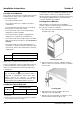
Section 2 Installation Instructions General These instructions are provided to assist the qualified installer. Dimensions 50.00cm 79.00cm 57.00cm 1.90cm±0.
Installation Instructions Section 2 Location of Ice Machine The location selected for the ice machine must meet the following criteria. If any of these criteria are not met, select another location. • The location must be indoors. • The location must be free of airborne and other contaminants. • The air temperature must be at least 1.6°C (35°F), but must not exceed 43.4°C (110°F). • The location must not be near heat-generating equipment or in direct sunlight.
Section 2 Installation Instructions Electrical Service ! Warning ! Warning All wiring must conform to local, state and national codes. Never use an extension cord. If an outlet is not within reach of the ice machine’s power cord, have a proper amperage outlet wired closer to the ice machine. Voltage Phase Total Amps 230/50/1 2.6 FUSE/CIRCUIT BREAKER 115/60/1 5.2 A separate fuse/circuit breaker must be provided for each ice machine.
Installation Instructions Section 2 Water Service/Drains WATER SUPPLY Local water conditions may require treatment of the water to inhibit scale formation, filter sediment, remove chlorine, and improve taste and clarity. • Install a water shut-off valve for both the ice making and condenser water lines (if applicable). • Insulate water lines to prevent condensation.
Section 2 Installation Instructions ICE MAKING WATER INLET TUBING 3/8” MIN.I.D. WATER SHUTOFF ICE MAKING WATER/BIN DRAIN 5/8” MIN.I.D.
Installation Instructions Installation Checklist Is the ice machine level? Section 2 Before Starting the Ice Machine All Manitowoc ice machines are factory-operated and adjusted before shipment. Normally, new installations do not require any adjustment. Has all of the internal packing been removed? To ensure proper operation, follow the Operational Checks on page 3-4 of this manual. Starting the ice machine and completing the Operational Checks are the responsibilities of the owner/operator.
Section 3 Operation Component Identification ICE THICKNESS PROBE FLOAT VALVE ASSEMBLY WATER DISTRIBUTION BIN SWITCH MAGNET ICE DAMPER WATER PUMP WATER TROUGH CONDENSER AIR FILTER ON/OFF/WASH TOGGLE SWITCH Part Number 000001774 07/08 3-1
Operation Section 3 Ice Making Sequence of Operation INITIAL START-UP OR START-UP AFTER AUTOMATIC SHUT-OFF 1. Pressure Equalization Before the compressor starts the hot gas valve is energized for 15 seconds to equalize pressures during the initial refrigeration system start-up. 2. Refrigeration System Start-Up The compressor starts after the 15-second pressure equalization, and remains on throughout the entire Freeze and Harvest Sequences.
Section 3 Operation Energized Parts Chart CONTROL BOARD RELAYS 1 2 3 WATER HOT GAS RELAY PUMP VALVE COIL INITIAL START-UP/ START UP AFTER AUTO SHUT-OFF: RELAY 3A COMPRESSOR 3B CONDENSER ∗ FAN MOTOR LENGTH of “ON” TIME OFF ON OFF OFF OFF 15 Seconds OFF ON ON ON ON 5 Seconds OFF OFF ON ON ON 30 Seconds 1. Pressure Equalization 2. Refrigeration System Start-up FREEZE SEQUENCE: 3. Pre-Chill 4. Freeze HARVEST SEQUENCE: ON OFF ON ON ON Until 7 sec.
Operation Section 3 Operational Checks GENERAL WATER FLOAT VALVE CHECK Your Manitowoc ice machine was factory-operated and adjusted before shipment. Normally, a newly installed ice machine does not require any adjustment. Before water will flow into the water trough the float valve shut-off must be in the OPEN position.
Section 3 Operation WATER LEVEL CHECK ICE BRIDGE THICKNESS CHECK Check the water level while the ice machine is in the ice mode and the water pump is running. The correct water level is 1/4”(6.3mm) to 3/8” (9.5mm) below the top of the standpipe a line in the water trough indicates the correct level. The ice thickness probe is factory-set to maintain the ice bridge thickness at 1/8” (3.2 mm). SIPHON CAP 1. Inspect the bridge connecting the cubes. It should be about 1/8” (3.2 mm) thick. 2.
Operation Section 3 THIS PAGE INTENTIONALLY LEFT BLANK 3-6 Part Number 000001774 07/08
Section 4 Maintenance Interior Cleaning and Sanitizing GENERAL Clean and sanitize the ice machine every six months for efficient operation. If the ice machine requires more frequent cleaning and sanitizing, consult a qualified service company to test the water quality and recommend appropriate water treatment. The ice machine must be taken apart for cleaning and sanitizing. ! Caution Use only Manitowoc approved Ice Machine Cleaner (part number 94-0546-3) and Sanitizer (part number 94-0565-3).
Maintenance Section 4 D. Remove the Water Distribution Tube C. Remove the Ice Thickness Probe • Compress the side of the ice thickness probe near the top hinge pin and remove it from the bracket. ICE THICKNESS PROBE 2 3 1. LIFT UP 2. SLIDE BACK 3. SLIDE TO RIGHT 1 DISTRIBUTION TUBE THUMBSCREW LOCATING PIN THUMBSCREW COMPRESS SIDES OF ICE THICKNESS PROBE Ice Thickness Probe Removal NOTE: At this point, the ice thickness probe can easily be cleaned.
Section 4 Maintenance F. Remove the Water Trough E. Remove the Float Valve • Turn the splash shield counterclockwise one or two turns. FLOAT VALVE BRACKET COMPRESSION FITTING • Apply downward pressure on the siphon tube and remove from the bottom of the water trough. • Remove the upper thumbscrew. • While supporting the water trough remove the two thumbscrews from beneath the water trough. • Remove the water trough from the bin area.
Maintenance Section 4 H. Remove the Bin Door G. Remove the ice damper. • Grasp ice damper and apply pressure toward the left hand mounting bracket. • Apply pressure to the right hand mounting bracket with thumb. • Pull ice damper forward when the right hand ice damper pin disengages. • Grasp the rear of the bin door and pull bin door forward approximately 5”.
Section 4 Maintenance Step 7 Mix a solution of cleaner and warm water. Depending on the amount of mineral buildup, a larger quantity of solution may be required. Use the ratio in the table below to mix enough solution to thoroughly clean all parts. Solution Type Water Mixed with Cleaner 1 gal. (4 l) 16 oz (500 ml) cleaner Step 8 Use ½ of the cleaner/water solution to clean all components.
Maintenance Section 4 Ice Machine Inspection Check all water fittings and lines for leaks. Also, make sure the refrigeration tubing is not rubbing or vibrating against other tubing, panels, etc. Do not put anything (boxes, etc.) in front of the ice machine. There must be adequate airflow through and around the ice machine to maximize ice production and ensure long component life. Exterior Cleaning Clean the area around the ice machine as often as necessary to maintain cleanliness and efficient operation.
Section 5 Before Calling for Service Checklist If a problem arises during operation of your ice machine, follow the checklist below before calling service. Routine adjustments and maintenance procedures are not covered by the warranty. Problem Ice machine does not operate. Possible Cause No electrical power to the ice machine. ON/OFF/ WASH toggle switch set improperly. Damper in open position (down). Ice machine stops, and can be restarted by moving the toggle switch to OFF and back to ICE.
Before Calling for Service Problem Ice machine produces shallow or incomplete cubes, or the ice fill pattern on the evaporator is incomplete. Section 5 Possible Cause Ice thickness probe is out of adjustment. To Correct Adjust the ice thickness probe. Water trough level is to high or too low. Water float valve filter screen is dirty. Water filtration is poor. Hot incoming water. Check the water level. Remove and clean the filter screen. Replace the filter.
Section 5 SAFETY LIMITS General In addition to standard safety controls, the control board has two built in safety limit controls which protect the ice machine from major component failures. Safety Limit #1: If the freeze time reaches 60 minutes, the control board automatically initiates a harvest cycle. If three consecutive 60-minute freeze cycles occur, the ice machine stops. Safety Limit #2: If the harvest time reaches 3.
Before Calling for Service Section 5 Safety Limit #1 Freeze time exceeds 60 minutes for 3 consecutive freeze cycles. Possible Cause Improper installation Water system Electrical system Restricted condenser air flow Refrigeration system Check/Correct See “Installation Instructions” Section 2 of this manual Low water pressure (20 psi minimum.) High water pressure (80 psi maximum.) High water temperature (90°F/32.2°C maximum.
Section 5 Before Calling for Service Safety Limit #2 Harvest time exceeds 3.5 minutes for 3 consecutive harvest cycles. Possible Cause Improper installation Water system Electrical system Refrigeration system Check/Correct See “Installation Instructions” Section 2 of this manual Water area (evaporator) dirty Water freezing behind evaporator Low water pressure (20 psi minimum.
Before Calling for Service Section 5 THIS PAGE INTENTIONALLY LEFT BLANK 5-6 Part Number 000001774 07/08
© 2007 Manitowoc Continuing product improvements may necessitate change of specifications without notice. Part Number 000001774 07/08 Manitowoc Foodservice Group 2110 South 26th Street, P.O. Box 1720 Manitowoc, WI 54221-1720, USA Ph: 920-682-0161 Fax: 920-683-7589 Visit us online at: www.manitowocfsg.