Flake/Nugget/Chiplet Ice Machines Technician’s Handbook This manual is updated as new information and models are released. Visit our website for the latest manual. www.manitowocfsg.
Safety Notices As you work on Manitowoc equipment, be sure to pay close attention to the safety notices in this handbook. Disregarding the notices may lead to serious injury and/or damage to the equipment. Throughout this handbook, you will see the following types of safety notices: ! Warning Text in a Warning box alerts you to a potential personal injury situation. Be sure to read the Warning statement before proceeding, and work carefully.
NOTE: Text set off as a Note provides you with simple, but useful, extra information about the procedure you are performing. Read These Before Proceeding: ! Caution Proper installation, care and maintenance are essential for maximum performance and troublefree operation of your Manitowoc equipment. If you encounter problems not covered by this handbook, do not proceed, contact Manitowoc Foodservice Group. We will be happy to provide assistance.
Table of Contents General Information Model Numbers . . . . . . . . . . . . . . . . . . 9 How to Read a Model Number . . . . . . 10 Model/Serial Number Location . . . . . . 11 Manitowoc Cleaner and Sanitizer . . . . 11 Ice Machine Warranty Information . . . 11 Installation Location of Ice Machine . . . . . . . . . . . 19 Ice Machine Clearance Requirements 20 Ice Machine Heat of Rejection . . . . . . 21 Location of Traditional Remote Units and Remote condensing units . . . . . . . . . .
Operation S Model Nugget/Flake Machines . . . . Q Model Flake/Chiplet Machines . . . . QF2200 . . . . . . . . . . . . . . . . . . . . . . . QF2300 . . . . . . . . . . . . . . . . . . . . . . . 115 119 122 128 Troubleshooting Operational Problem Checklist . . . . . . 141 Water System Checklist . . . . . . . . . . . 146 SafeGuard Feature . . . . . . . . . . . . . . . 147 Component Check Procedures Main Fuse . . . . . . . . . . . . . . . . . . . . . . 167 Float Switch . . . . . . . . . . . . . . . . . . . .
Component Specifications Main Fuse . . . . . . . . . . . . . . . . . . . . . . 247 Bin Switch . . . . . . . . . . . . . . . . . . . . . . 247 ICE/OFF/CLEAN Toggle Switch . . . . . 247 Fan Cycle Control . . . . . . . . . . . . . . . . 247 High Pressure Cutout (HPCO) . . . . . . 247 Torque Values . . . . . . . . . . . . . . . . . . . 247 Gearmotor RPMs . . . . . . . . . . . . . . . . 248 Filter-Driers . . . . . . . . . . . . . . . . . . . . . 248 Suction Line Filter . . . . . . . . . . . . . . . .
SN1250A . . . . . . . . . . . . . . . . . . . . . . SN1250W . . . . . . . . . . . . . . . . . . . . . . SN1250C/RFC1285 . . . . . . . . . . . . . . QF2200/RFC2085 . . . . . . . . . . . . . . . QF2300/RFC2385 . . . . . . . . . . . . . . . Diagrams Wiring Diagrams . . . . . . . . . . . . . . . . . . . SN012/SN020 . . . . . . . . . . . . . . . . . . . S Model Flake / Nugget . . . . . . . . . . . QF0400 . . . . . . . . . . . . . . . . . . . . . . . . QC0700/QF0800 . . . . . . . . . . . . . . . . QF2200 . . . .
General Information MODEL NUMBERS Head Section Models SelfContained Air-Cooled SelfTraditional Remote Contained Remote Condensing Water-Cooled Condenser Unit SN012A (T) NA NA NA SN020A (T) NA N/A NA QF0406A NA NA NA SF0406A SN0407W NA NA SN0458A SN0459W NA NA SF0606A SF0607W SF0696N NA SN0658A SN0659W SN0698N NA QC0708A QC0709W NA NA QF0806A QF0807W NA NA SF0906A SF0907W NA SF0976C SN0958A SN0959W NA SN0978C SF1206A SF1207W NA SF1276C SN1258A SN1259W NA S
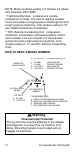
NOTE: Model numbers ending in 3 indicate a 3-phase unit. Example: RFC12853 * Traditional Remotes - condenser is outside, compressor is inside. The heat is rejected outside. Line set consists of a high pressure discharge line and a high pressure liquid line. Only models ending in “N” use Traditional Remote Condensers. ** RFC Remote Condensing Unit - compressor, condenser, accumulator and head pressure control valve outside. Line set consists of a low pressure suction line and a high pressure liquid line.
MODEL/SERIAL NUMBER LOCATION These numbers are required when requesting information from your local Manitowoc Distributor, service representative, or Manitowoc Ice, Inc. The model and serial number are listed on the OWNER WARRANTY REGISTRATION CARD. They are also listed on the MODEL/SERIAL NUMBER DECAL affixed to the ice machine. MANITOWOC CLEANER AND SANITIZER Manitowoc Ice Machine Cleaner and Sanitizer are available in 16 oz. (473 ml) bottles.
Commercial Warranty Coverage GENERAL The following Warranty outline is provided for your convenience. For a detailed explanation, read the warranty bond shipped with each product. Contact your local Manitowoc representative or Manitowoc Ice, Inc. if you need further warranty information. PARTS 1. Manitowoc warrants the ice machine against defects in materials and workmanship, under normal use and service for three (3) years from the date of original installation. 2.
4. Premium labor rates due to holidays, overtime, etc.; travel time; flat rate service call charges; mileage and miscellaneous tools and material charges not listed on the payment schedule. Additional labor charges resulting from the inaccessibility of equipment are also excluded. 5. Parts or assemblies subjected to misuse, abuse, neglect or accidents. 6. Damage or problems caused by installation, cleaning and/or maintenance procedures inconsistent with the technical instructions provided in this manual.
RESIDENTIAL ICE MACHINE LIMITED WARRANTY WHAT DOES THIS LIMITED WARRANTY COVER? Subject to the exclusions and limitations below, Manitowoc Ice, Inc. (“Manitowoc”) warrants to the original consumer that any new ice machine manufactured by Manitowoc (the “Product”) shall be free of defects in material or workmanship for the warranty period outlined below under normal use and maintenance, and upon proper installation and startup in accordance with the instruction manual supplied with the Product.
WHAT ARE MANITOWOC ICE’S OBLIGATIONS UNDER THIS LIMITED WARRANTY? If a defect arises and Manitowoc receives a valid warranty claim prior to the expiration of the warranty period, Manitowoc shall, at its option: (1) repair the Product at Manitowoc’s cost, including standard straight time labor charges, (2) replace the Product with one that is new or at least as functionally equivalent as the original, or (3) refund the purchase price for the Product.
WHAT IS NOT COVERED? This limited warranty does not cover, and you are solely responsible for the costs of: (1) periodic or routine maintenance, (2) repair or replacement of the Product or parts due to normal wear and tear, (3) defects or damage to the Product or parts resulting from misuse, abuse, neglect, or accidents, (4) defects or damage to the Product or parts resulting from improper or unauthorized alterations, modifications, or changes; and (5) defects or damage to any Product that has not been inst
IN NO EVENT SHALL MANITOWOC OR ANY OF ITS AFFILIATES BE LIABLE TO THE CONSUMER OR ANY OTHER PERSON FOR ANY INCIDENTAL, CONSEQUENTIAL OR SPECIAL DAMAGES OF ANY KIND (INCLUDING, WITHOUT LIMITATION, LOSS OF PROFITS, REVENUE OR BUSINESS) ARISING FROM OR IN ANY MANNER CONNECTED WITH THE PRODUCT, ANY BREACH OF THIS LIMITED WARRANTY, OR ANY OTHER CAUSE WHATSOEVER, WHETHER BASED ON CONTRACT, TORT OR ANY OTHER THEORY OF LIABILITY.
This Page Intentionally Left Blank 18 Part Number 80-1230-9 6/08
Installation ! Warning PERSONAL INJURY POTENTIAL Remove all ice machine panels before lifting and installing. LOCATION OF ICE MACHINE The location selected for the ice machine must meet the following criteria. If any of these criteria are not met, select another location. • The location must be indoors. • The location must be free of airborne and other contaminants. • The air temperature must be at least 45°F (7°C), but must not exceed 110°F (43°C).
ICE MACHINE CLEARANCE REQUIREMENTS SN12/SN20 Self-Contained Air-Cooled Water-Cooled* Top 24" (61.0 cm) NA Sides 8" (20.3 cm) NA Back 5" (12.7 cm) NA QF400 Self-Contained Air-Cooled Water-Cooled and Remote* Top/Sides 5" (12.7 cm) NA Back 5" (12.7 cm) NA SF400/SN450 SF600/SN650 SF900/SN950 S1200/SN1250 Self-Contained Air-Cooled Water-Cooled and Remote* Top/Sides 8" (20.3 cm) 8" (20.3 cm)* Back 5" (12.7 cm) 5" (12.
ICE MACHINE HEAT OF REJECTION Series Ice Machine Heat of Rejection* SN12/SN20 2,300 QF400 4,000 SF400/SN450 3,400 Air Conditioning SF600/SN650 5,300 QF800/QC700 7,800 SF900/SN950 SF900C/SN950C 9,000 SF1200/SN1250 SF1200C/SN1250C 16,000 QF2200/QF2300 * BTU/Hour 21,000 Because the heat of rejection varies during the ice making cycle, the figure shown is an average. Ice machines, like other refrigeration equipment, reject heat through the condenser.
LOCATION OF TRADITIONAL REMOTE UNITS AND REMOTE CONDENSING UNITS The location selected for the Remote Units must meet the following criteria. If any of these criteria are not met, select another location. • The air temperature must be at least -20°F (-28.9°C) but must not exceed 120°F (49°C). • The location must not allow exhaust fan heat and/ or grease to enter the condenser. • The location must not obstruct airflow through or around the condensing unit. Refer to the chart below for clearance requirements.
ELECTRICAL SERVICE General ! Warning All wiring must conform to local, state and national codes. Voltage The maximum allowable voltage variation is ± 10% of the rated voltage on the ice machine model/serial number plate at start-up (when the electrical load is highest). Fuse/Circuit Breaker A separate fuse/circuit breaker must be provided for each ice machine. Circuit breakers must be H.A.C.R. rated (does not apply in Canada).
Circuit Ampacity The minimum circuit ampacity is used to help select the wire size of the electrical supply. (Minimum circuit ampacity is not the ice machine’s running amp load.) The wire size (or gauge) is also dependent upon location, materials used, length of run, etc., so it must be determined by a qualified electrician. Self Contained Air-Cooled Max. Fuse/ Circuit Breaker Total Amps 115/1/60 15 10.3 230/1/50 15 4.6 115/1/60 15 9.8 230/1/50 15 4.2 Voltage Phase Cycle Max.
Ice Machine Voltage Phase Cycle Max. Fuse/ Circuit Breaker Minimum Circuit Amps Air-Cooled QC0700/ QF0800 115/1/60 30 18.9 230/1/50 20 8.8 230/1/60 15 8.7 Water-Cooled 115/1/60 30 17.9 230/1/50 20 8.4 230/1/60 15 8.3 Air-Cooled SF0900/ SN0950 SF0900C/ SN0950C 230/1/50 15 7.0 230/1/60 15 8.0 Water-Cooled 230/1/50 15 6.7 230/1/60 15 7.7 Air-Cooled Head Section 115/1/60 15 1.7 Air-Cooled SF1200/ SN1250 SF1200C/ SN1250C QF2200 QF2300 230/1/50 15 8.0 230/1/60 15 9.
Condensing Unit RFC0985 used with SF0900C/ SN0950C RFC1285 used with SF1200C/ SN1250C RFC2085 used with QF2200 RFC2385 used with QF2300 26 Voltage Phase Cycle Max. Fuse/ Circuit Breaker Minimum Circuit Amps Remote Condensing Unit 208-230/1/60 15 8.6 208-230/1/50 15 8.0 Remote Condensing Unit 208-230/1/60 15 208-230/3/60 15 9.2 6.8 208-230/1/50 15 12.0 Remote Condensing Unit 208-230/1/60 30 15.6 208-230/3/60 20 11.2 Remote Condensing Unit 208-230/1/60 30 18.
ICE MACHINE HEAD SECTION WATER SUPPLY AND DRAINS Potable Water Supply Local water conditions may require treatment of the water to inhibit scale formation, filter sediment, remove chlorine, and improve taste and clarity. Important If you are installing a Manitowoc water filter system, refer to the Installation Instructions supplied with the filter system for ice making water inlet connections.
Drain Connections Follow these guidelines when installing drain lines to prevent drain water from flowing back into the ice machine and storage bin: • Drain lines must have a 1.5 in. (3.8 cm) drop per 5 ft. of run (2.5 cm per meter), and must not create traps. • The floor drain must be large enough to accommodate drainage from all drains. • Run separate bin and water-cooled condenser drain lines. Insulate them to prevent condensation. • Vent the bin drain to the atmosphere.
INSTALLING ON A DISPENSER Nugget ice is soft and chewable. This characteristic makes this ice more difficult to dispense. All dispenser manufacturers require a kit be installed for Nugget type ice. Contact the dispenser manufacturer for the correct adapter and nugget dispensing kit for your specific model dispenser. The required kit can vary by dispenser size from the same manufacturer.
LINE SET REQUIREMENTS Traditional Remote Units Only Ice Machine Head Section Condenser Line Set SN0650 JC0495 RM-20 RM-35 RM-50 Line Set Discharge Line Liquid Line Insulation Thickness RM20/35/50 5/16 in (7.9 mm) 1/4 in (7 mm) 1/2 in 12.
• • • • • Maximum total amount of tubing is 100’ (30.5 M) Maximum height condenser or condensing unit can be above ice machine is 35’ (10.7 M) Maximum distance condenser or condensing unit can be below the ice machine 15’ (4.5 M) Condensing units only - Suction line oil trap is required for any rise that is 20’ (6 M) or greater. Refer to Installation Use and Care Manual for complete installation information. Important Manitowoc remote systems are only approved and warranted as a complete new package.
This Page Intentionally Left Blank 32 Part Number 80-1230-9 6/08
Component Identification ICE MACHINE HEAD SECTION S Model Flake/Nugget Machines AIR BAFFLE ELECTRICAL ENTRANCE ICE CHUTE GEAR MOTOR COMPRESSOR AIR-COOLED CONDENSER FAN MOTOR WATER INLET WATER RESERVOIR AIR-COOLED CONDENSER EVAPORATOR DUMP VALVE GEAR BOX Part Number 80-1230-9 6/08 DRAIN FITTING 33
GEAR MOTOR ICE CHUTE COVER HALL EFFECT SWITCH WATER RESERVOIR CONTROL BOARD CONTROL BOX TOGGLE SWITCH COOL VAPOR VALVE HALL EFFECT SWITCH QuietQube Only SUCTION LINE & LIQUID LINE CONTROL BOX WATER INLET DRIER EXPANSION VALVE RECEIVER WATER RESERVOIR GEAR MOTOR WATER DUMP VALVE EVAPORATOR Remote & QuietQube Models 34 Part Number 80-1230-9 6/08
QF800/QC700 WATER LEVEL PROBE CLEANING SOLUTION FILL HOLE DUMP VALVE CONDENSER FAN MOTOR ICE CHUTE ICE/OFF/CLEAN TOGGLE SWITCH Part Number 80-1230-9 6/08 35
QF400 WATER FLOAT VALVE COIL WATER LEVEL PROBES EVAPORATOR CONTROL BOX POTABLE WATER DRAIN ICE/OFF/CLEAN TOGGLE SWITCH GEAR MOTOR / GEAR BOX ASSEMBLY CONDESER FAN/ MOTOR 36 Part Number 80-1230-9 6/08
Maintenance Maintenance procedures or failures due to a lack of maintenance are not covered by the warranty. Manitowoc Ice Machine Cleaner and Sanitizer are the only products approved for use in Manitowoc ice machines. ! Caution Use the correct Manitowoc approved metal safe Ice Machine Cleaner (part number 000000084) and Sanitizer (part number 94-0565-3). It is a violation of Federal law to use these solutions in a manner inconsistent with their labeling.
Cleaning/Sanitizing Procedure This procedure must be performed a minimum of once every six months: • All ice must be removed from the bin/dispenser. • The ice machine and bin/dispenser must be disassembled, cleaned and sanitized. • The ice machine produces ice with the cleaner and sanitizer solutions. • All ice produced during the cleaning and sanitizing procedure must be discarded.
EXTERIOR CLEANING Clean the area around the ice machine as often as necessary to maintain cleanliness and efficient operation. Use cleaners designed for use with stainless steel products. Sponge any dust and dirt off the outside of the ice machine with mild soap and water. Wipe dry with a clean, soft cloth. Heavy stains should be removed with stainless steel wool. Never use plain steel wool or abrasive pads. They will scratch the panels.
CLEANING THE CONDENSER ! Warning Disconnect electric power to the ice machine at the electric service switch before cleaning the condenser. The condenser fins are sharp. Use care when cleaning them. Air-Cooled Condenser A dirty condenser restricts airflow, resulting in excessively high operating temperatures. This reduces ice production and shortens component life. Clean the condenser at least every six months. Follow the steps below. 1.
Water-Cooled Condenser and Water Regulating Valve Symptoms of restrictions in the condenser water circuit include: • Low ice production • High water consumption • High operating temperatures • High operating pressures If the ice machine is experiencing any of these symptoms, the water-cooled condenser and water regulating valve may require cleaning due to scale build-up. The cleaning procedures require special pumps and cleaning solutions.
MANITOWOC’S CLEANING TECHNOLOGY Manitowoc Flake/Nugget Ice Machines include technology that allows the initiation and completion of a cleaning cycle at the flip of a switch. This cycle will permit cleaning of all surfaces that come in contact with the water distribution system. Periodic maintenance must be performed that includes sanitizing the bin and adjacent surface areas, which are not contacted by the water distribution system.
Heavily Scaled Cleaning Procedure Perform this procedure if you have some or all of these symptoms. • Grinding, popping or squealing noises from the evaporator • Grinding noise from gearbox • Ice machine stops on Safety Shutdown • Your water has a high concentration of minerals • The ice machine has not been on a regular maintenance schedule. Run a cleaning procedure as described above after this procedure is complete.
S MODEL NUGGET/FLAKE MACHINES Preventative Maintenance Ice machine cleaner is used to remove lime scale or other mineral deposits. It is not used to remove algae or slime. Refer to “Sanitizing Procedure” for removal of algae and slime. To initiate a cleaning cycle using Manitowoc’s Cleaning Technology use the following procedure. Step 1 To start a cleaning cycle, move the toggle switch to the CLEAN position. Water will flow through the water dump valve and down the drain.
ADD SOLUTION HERE Step 3 The ice machine will automatically time out a series of flush and rinse cycles, and then stops. This entire cycle lasts approximately 30 minutes. NOTE: Periodic cleaning must be performed on adjacent surface areas not contacted by the water distribution system. NOTE: The ice machine may be set to start and finish a cleaning procedure, and then automatically start ice making again. A. After cleaner is added move the switch from CLEAN to ICE position. B.
Changing toggle switch position during clean cycle: 1. Less than 60 seconds into Clean cycle - The Clean cycle will end when the toggle switch is moved to the OFF position. 2. More than 60 seconds into Clean cycle - The ice machine will complete the clean cycle. Toggle switch position will determine the next cycle after the Clean cycle is completed. • CLEAN POSITION - The ice machine will wait for a change in toggle switch position.
Procedure to Clean Heavily Scaled Flake/Nugget Ice Machines Ice machines that are heavily scaled or have not been cleaned on a regular basis will need to run this Procedure. Failure to do so may result in binding of the auger as the lime scale releases from the auger and evaporator barrel. Step 1 Remove panels and set the ICE/OFF/CLEAN toggle switch to the OFF position. Step 2 Remove all ice from the bin. Step 3 Turn off the water supply to the ice machine.
ADD SOLUTION HERE Step 1 Turn on the water supply to the ice machine. Important Leave the cleaner/water solution evaporator for a minimum of 4 hours. in the Step 2 Move the toggle switch to the ICE position. The compressor will energize and produce ice with the cleaning solution. Continue the freeze cycle for 15 minutes. Step 3 Move the toggle switch to the OFF position, then follow the standard cleaning and sanitizing procedures.
Cleaning Procedure Ice machines that are heavily scaled or have not been cleaned on a regular basis will need to run the Heavily Scaled Cleaning Procedure before this one. Failure to do so may result in binding of the auger as the lime scale releases from the auger and evaporator barrel. Ice machine cleaner is used to remove lime scale or other mineral deposits. It is not used to remove algae or slime. Refer to the “Sanitizing Procedure” for removal of algae and slime.
Step 6 Refer to chart and premix the correct solution of cleaner and cool water for your model ice machine.
Sanitizing Procedure Ice machine sanitizer is used to remove algae or slime. It is not used to remove lime scale or other mineral deposits. Refer to the “Cleaning Procedure” for removal of lime scale or other mineral deposits. NOTE: Sanitizing must be performed on adjacent surface areas not contacted by the water distribution system. Always perform Disassembly for Cleaning and Sanitizing Procedure and a Cleaning Procedure before sanitizing the ice machine.
Step 8 Move the toggle switch to the ICE position. The compressor will energize and produce ice with the sanitizing solution. Step 9 The ice machine will freeze and discharge the sanitizing solution into the bin. Allow the cycle to run for 15 minutes. Step 10 Discard all ice produced during the sanitizing process. Step 11 Place the toggle switch in the CLEAN position. The ice machine will automatically time out a series of flush and rinse cycles, and then stops.
COMPONENT DISASSEMBLY FOR CLEANING AND SANITIZING SF400/SN450/SF600/SN650/SF900/SN950/SF1200/ SN1250 The ice machine must be disassembled cleaned and sanitized every six months. ! Warning Wear rubber gloves and safety goggles (and/or face shield) when handling Ice Machine Cleaner or Sanitizer. 1. Remove front, side and top panels. 2. Perform the cleaning and sanitizing procedures. 3. Run the ice machine in the freeze cycle for 5 minutes, then place the toggle switch in the OFF position. 4.
1. Disconnect the water supply. 2. Reconnect the main power supply to the ice machine. 3. Place toggle switch in the clean position for 30 seconds to drain water from reservoir, then move the toggle switch to the Off position. 4. Disconnect the main power supply to the ice machine. ! Warning Disconnect electric power to the ice machine at the electric switch box before proceeding.
5. Lift out ice damper. 6. Lift out ice strainer ramp.
7. Loosen ice chute hose clamp. 8. Disconnect ice chute drain. ICE CHUTE DRAIN AND HOSE CLAMP 9. Lift up on ice chute to remove.
10. The ice chute can be cleaned in place. If complete removal is desired use a phillips screwdriver to remove the Hall Effect Switch assembly from the ice chute. REMOVE SCREW 11. Remove ice chute collar and tube by lifting straight up.
12. Remove water reservoir cover by pushing up on cover to snap off. The water reservoir can be cleaned in place.
! Caution Do not mix Cleaner and Sanitizer solutions together. It is a violation of Federal law to use these solutions in a manner inconsistent with their labeling. 13. Mix a solution of cleaner and warm water. Depending upon the amount of mineral buildup, a larger quantity of solution may be required. Use the ratio in the table below to mix enough solution to thoroughly clean all parts. Solution Type Cleaner Water Mixed With 1 gal. (4 l) 16 oz (500 ml) cleaner 14.
17. Use 1/2 of the sanitizer/water solution to sanitize all removed components. Use a cloth or sponge to liberally apply the solution to all surfaces of the removed parts or soak the removed parts in the sanitizer/water solution. Do not rinse parts after sanitizing. 18. Use 1/2 of the sanitizer/water solution to sanitize the bin (or dispenser). Use a cloth or sponge to liberally apply the solution. Do not rinse the sanitized areas. 19.
SN012/SN020 1. Turn off water supply to ice machine. 2. Place toggle switch in the clean position for 30 seconds to drain water from reservoir, then move toggle switch to Off position. 3. Run dispenser to transfer all ice from the bin to a container. ! Warning Disconnect electric power to the ice machine at the electric switch box before proceeding. 4. Disconnect electrical power to the ice machine. 5. Remove top cover. A. Remove two screws. B. Lift up on top cover to remove.
6. Remove front cover. A. Lift up on front cover. B. Pull forward to disengage keyhole slots. 7. Remove side panels.
8. Remove ice chute cover A. Turn the two thumbscrews 1/4 turn. B. Lift to remove cover.
9. Lift out ice damper.
10. Lift out ice strainer ramp.
11. Turn ice wiper counterclockwise to remove.
12. Loosen ice chute hose clamp. 13. Disconnect ice chute drain.
14. Lift up on ice chute to remove. The ice chute must be removed before the bin cover can be removed.
15. The ice chute can be cleaned in place. If complete removal is desired use a phillips screwdriver to remove the Hall Effect Switch assembly from the ice chute.
16. Remove three thumbscrews, then remove bin cover.
17. Remove agitator bar. • SN012 - Remove the thumbscrew and lift off. • SN020 - Unscrew the upright agitator bar. NOTE: Bar must be reassembled by inserting front edge into the paddle wheel, then lowering the back edge (rounded 90 angle) to prevent water leakage into the compressor compartment.
18. Remove ice deflector. A. Remove the two thumbscrews. B. Lift the ice deflector out.
19. Remove ice dispensing wheel by lifting straight out.
20. Water Reservoir Cover Removal A. Push up on cover to snap off. 21. Mix a solution of cleaner and warm water. Depending upon the amount of mineral buildup, a larger quantity of solution may be required. Use the ratio in the table below to mix enough solution to thoroughly clean all parts. Solution Type Water Mixed With Cleaner 1 gal. (4 l) 16 oz (500 ml) cleaner 22. Use the cleaner/water mixture to clean all components.
23. While components are soaking clean all foodzone surfaces of the bin. Rinse all areas thoroughly with clean water. SN12/SN20 Do not allow solutions to drain through center hole 24. Mix a solution of sanitizer and warm water. Solution Type Water Mixed With Sanitizer 6 gal. (23 l) 4 oz (120 ml) sanitizer 25. Use 1/2 of the sanitizer/water solution to sanitize all removed components.
Water Dump Valve - All Models The water dump valve normally does not require removal for cleaning. To determine if removal is necessary: 1. Set the toggle switch to OFF. 2. Watch the water float valve. If the dump valve is leaking the float will continue to add water in the Off cycle. • If the dump valve is leaking, remove, disassemble and clean it. • If the dump valve is not leaking, do not remove it. Instead, follow the “Cleaning Procedure”. Follow the procedure below to remove the dump valve.
4. Remove the tubing from the dump valve by twisting the clamps off. 5. Remove the valve body from mounting bracket by twisting counterclockwise. .
QF0400 Preventative Maintenance Cleaning Procedure Step 1 Set the toggle switch to the OFF position. Open bin door and remove the 2 thumbscrews and back evaporator panel. Step 2 To start a cleaning cycle, move the toggle switch to the CLEAN position. Water will flow through the water dump valve and down the drain. The flush, gear motor, speed, dump valve and water solenoid lights will energize to indicate the ice machine is in the cleaning mode.
NOTE: Periodic cleaning must be performed on adjacent surface areas not contacted by the water distribution system. Manitowoc recommends disassembling, cleaning and sanitizing the ice machine and bin/dispenser a minimum of once every six months. Step 5 A. The ice machine may be set to start and finish a cleaning procedure, and then automatically start ice making again. B. Wait about one minute into the cleaning cycle (until the Dump Valve light de-energizes), then move the switch from CLEAN to ICE position.
Cleaning Procedure QF400 Step 1 Set the toggle switch to the OFF position. Open bin door and remove the 2 thumbscrews and back evaporator panel. Step 2 To start a cleaning cycle, move the toggle switch to the CLEAN position. Water will flow through the water dump valve and down the drain. The flush, gear motor, speed, dump valve and water solenoid lights will energize to indicate the ice machine is in the cleaning mode. Step 3 Wait about 1 minute or until the dump valve light de-energizes.
NOTE: Periodic cleaning must be performed on adjacent surface areas not contacted by the water distribution system. Manitowoc recommends disassembling, cleaning and sanitizing the ice machine and bin/dispenser a minimum of once every six months. Step 5 A. The ice machine may be set to start and finish a cleaning procedure, and then automatically start ice making again. B. Wait about one minute into the cleaning cycle (until the Dump Valve light de-energizes), then move the switch from CLEAN to ICE position.
Sanitizing Procedure QF400 Ice machine sanitizer is used to remove algae or slime. It is not used to remove lime scale or other mineral deposits. Refer to “Cleaning Procedure” for removal of remove lime scale or other mineral deposits. Step 1 Perform cleaning procedure before sanitizing the ice machine. Step 2 Disconnect water supply line at float valve quick disconnect by depressing stainless steel lever. Step 3 Mix 2 oz. (60 ml) of Manitowoc Ice Machine Sanitizer with 3 gal. (11 L) of cool water.
Step 5 Wait 45 seconds until the Dump Valve light de-energizes and the Water Level Probe light energizes. Fill the water reservoir with the pre-mixed solution of sanitizer/water. When water contacts the water level probe, the compressor will energize. The ice machine will freeze and discharge the sanitizing solution into the bin. Add the remaining sanitizer/water solution when the water level in the reservoir drops. NOTE: Do not allow the water level to drop below the water level probes.
Procedure to Clean Heavily Scaled Ice Machines QF400 Step 1 Remove all ice from the bin. Step 2 Remove front and top covers and set the toggle switch to the OFF position. Step 3 Disconnect water supply line at float valve quick disconnect by depressing stainless steel lever. Step 4 Refer to chart below: Pre-mix cleaner with lukewarm water in a nonmetallic container. Model QF0400 Water Reservoir Capacity 48 oz (1.4 L) Mix Cleaner and Water Cleaner Water 32 oz (0.94 L) 16 oz (0.
Removal of Parts for Cleaning and Sanitizing QF400 1. Turn off the water supply to the ice machine at the water service valve, or disconnect water supply line at float valve quick disconnect by depressing stainless steel lever. ! Warning Disconnect electric power to the ice machine at the electric switch box before proceeding. 2. Remove the components you want to clean or sanitize. See the pages specific to the model you are working on for removal procedures for these parts.
Water Level Probe Removal 1. Place the toggle switch in the OFF position, turn off the water supply and disconnect electrical power to the ice machine. 2. Disconnect water supply line at float valve quick disconnect by depressing stainless steel lever. 3. Pull up on water level probes to remove. 4. Disconnect wires from water level probes or control board. WATER LEVEL PROBES QF0400 Water Reservoir Cover Removal 1.
Float Valve Removal 1. Place the toggle switch in the OFF position, turn off the water supply and disconnect electrical power to the ice machine. 2. Disconnect water supply line at float valve quick disconnect by depressing stainless steel lever. 3. Remove water float valve coil. 4. Depress coil and rotate 1/4 turn counterclockwise. 5. With coil wires attached, lift coil off enclosure tube. 6. Remove top cover from float reservoir. 7. Lift float valve out of float reservoir. Water Reservoir Removal 1.
Ice Diverter Removal 1. Place the toggle switch in the OFF position, turn off the water supply and disconnect electrical power to the ice machine. 2. Remove thumbscrews and lift panel forward. 3. Remove bin level sensor from white plastic panel. 4. Remove ice diverter from bin.
Bin Door Removal Door removal allows easier access for cleaning and sanitizing. 1. Disconnect the electrical power to the ice machine and remove ice from bin. 2. Grasp the rear of the bin door and pull bin door forward approximately 5”. 3. Slide bin door to the rear while applying upward pressure (the rear door pins will ride up into the track slot). 4. Slide the rear door pins off the end and then below the door track. Slide bin door forward allowing the back of the door to lower into the bin.
Cabinet Removal 1. Remove all ice from bin and disconnect power. 2. Remove thumbscrews and evaporator panel. 3. Remove three screws from the bottom of the left and right side of cabinet. 4. Remove nine screws from back panel. 5. Disconnect drain line clamp. 6. Slide cabinet forward and remove from base.
Water Dump Valve The water dump valve normally does not require removal for cleaning. To determine if removal is necessary: 1. Locate the water dump valve. 2. Set the toggle switch to ICE. 3. While the ice machine is in the freeze mode, check the drain for leakage. • If the dump valve is leaking, remove, disassemble and clean it. • If the dump valve is not leaking, do not remove it. Instead, follow the “Cleaning Procedure”. Follow the procedure below to disassemble the dump valve.
SPRING COIL NYLON WASHER PLUNGER DIAPHRAM MOUNTING BRACKET VALVE BODY Dump Valve Disassembly 92 Part Number 80-1230-9 6/08
QC0700/QF0800/QF2200/QF2300 Preventative Maintenance Cleaning Procedure Step 1 Remove front and top covers and set the toggle switch to the OFF position. Step 2 To start a cleaning cycle, move the toggle switch to the CLEAN position. Water will flow through the water dump valve and down the drain. The flush, gear motor, speed, dump valve and water solenoid lights will energize to indicate the ice machine is in the cleaning mode. Step 3 Remove the 1-1/2 in. plug from the top cover of the water reservoir.
NOTE: Periodic cleaning must be performed on adjacent surface areas not contacted by the water distribution system. Manitowoc recommends disassembling, cleaning and sanitizing the ice machine and bin/dispenser a minimum of once every six months. Step 5 A. The ice machine may be set to start and finish a cleaning procedure, and then automatically start ice making again. B. Wait about one minute into the cleaning cycle (until the Dump Valve light de-energizes), then move the switch from CLEAN to ICE position.
Cleaning Procedure QC0700/QF0800/QF2200/QF2300 Ice machine cleaner is used to remove lime scale or other mineral deposits. It is not used to remove algae or slime. Refer to “Sanitizing Procedure” for removal of algae and slime. Step 1 Remove front and top cover and set the toggle switch to the OFF position. Step 2 Remove all ice from the bin/dispenser. Step 3 Disconnect water supply line at float valve quick disconnect by depressing stainless steel lever.
Step 7 Wait 45 seconds until the Dump Valve light de-energizes and the Water Level Probe light energizes. Add the proper amount of Manitowoc Ice Machine Cleaner to the water reservoir.. ! Caution Use Manitowoc clear (P/N 000000084) Ice Machine Cleaner only. It is a violation of Federal law to use these solutions in a manner inconsistent with their labeling. Read and understand all labels printed on bottles before use. Model Amount of Cleaner (Part #000000084) QF0800/QC0700 3 oz.
Sanitizing Procedure QF0800/QC0700/QF2200/QF2300 Ice machine sanitizer is used to remove algae or slime. It is not used to remove lime scale or other mineral deposits. Refer to “Cleaning Procedure” for removal of remove lime scale or other mineral deposits. Step 1 Perform cleaning procedure before sanitizing the ice machine. Step 2 Disconnect water supply line at float valve quick disconnect by depressing stainless steel lever. Step 3 Mix 2 oz. (60 ml) of Manitowoc Ice Machine Sanitizer with 3 gal.
Step 5 Wait 45 seconds until the Dump Valve light de-energizes and the Water Level Probe light energizes. Fill the water reservoir with the pre-mixed solution of sanitizer/water. When water contacts the water level probe, the compressor will energize. The ice machine will freeze and discharge the sanitizing solution into the bin. Add the remaining sanitizer/water solution when the water level in the reservoir drops. NOTE: Do not allow the water level to drop below the water level probes.
Procedure to Clean Heavily Scaled Ice Machines QC0700/QF0800/QF2200/QF2300 Step 1 Remove all ice from the bin. Step 2 Remove front and top covers and set the toggle switch to the OFF position. Step 3 Disconnect water supply line at float valve quick disconnect by depressing stainless steel lever. Step 4 Refer to chart below: ! Caution Use Manitowoc clear (P/N 000000084) Ice Machine Cleaner only. It is a violation of Federal law to use these solutions in a manner inconsistent with their labeling.
Step 5 Remove all water from the evaporator and water reservoir. Start an ice making cycle by moving the toggle switch to the ICE position. Water will flow through the water dump valve and down the drain for 45 seconds. After 45 seconds move the toggle switch to the OFF position. Remove the plug from the top cover of the water reservoir. Add the entire cleaner/ water solution and re-install the plug. Leave the cleaner/water solution in the evaporator for a minimum of 4 hours.
Removal of Parts for Cleaning or Sanitizing QC0700/QF0800/QF2200/QF2300 1. Turn off the water supply to the ice machine at the water service valve, or disconnect water supply line at float valve quick disconnect by depressing stainless steel lever. ! Warning Disconnect electric power to the ice machine at the electric switch box before proceeding. 2. Remove the components you want to clean or sanitize. See pages specific to the model you are working on for removal procedures for these parts.
Water Level Probe Removal 1. Place the toggle switch in the OFF position, turn off the water supply and disconnect electrical power to the ice machin.e. 2. Disconnect water supply line at float valve quick disconnect by depressing stainless steel lever. 3. Pull up on water level probes to remove. 4. Disconnect wires from water level probes or control board.
Water Reservoir Cover Removal 1. Place the toggle switch in the OFF position, turn off the water supply and disconnect electrical power to the ice machine. 2. Remove water level probes. 3. Remove water float valve coil. A. Depress coil and rotate 1/4 turn counterclockwise. B. With coil wires attached, lift coil off enclosure tube. 4. QF0800/QC0700 ONLY Rotate quarter turn fasteners counterclockwise. 5. QF0800/QC0700 ONLY Remove cotter key and pin from ice chute. 6. Remove top cover from float reservoir.
Water Reservoir Cover Removal QF2200/QF2300 1. Place the toggle switch in the OFF position, turn off the water supply and disconnect electrical power to the ice machine. 2. Remove water level probes. 3. Remove water float valve coil. 4. Depress coil and rotate 1/4 turn counterclockwise. 5. With coil wires attached, lift coil off enclosure tube. 6. Remove top cover from float reservoir.
Float Valve Removal 1. Place the toggle switch in the OFF position, turn off the water supply and disconnect electrical power to the ice machine. 2. Disconnect water supply line at float valve quick disconnect by depressing stainless steel lever. 3. Remove water float valve coil. A. Depress coil and rotate 1/4 turn counterclockwise. B. With coil wires attached, lift coil off enclosure tube. 4. QF0800/QC0700 ONLY Rotate quarter turn fasteners counterclockwise. 5.
Water Reservoir Removal 1. Place the toggle switch in the OFF position and turn off the water supply to the ice machine at the water service valve. 2. Disconnect water supply line at float valve quick disconnect by depressing stainless steel lever. 3. Place the toggle switch in the ICE position. The dump valve will open and the float reservoir will empty. 4. After the reservoir is empty, place the toggle switch in the OFF position and disconnect power to the ice machine at the service disconnect. 5.
Ice Chute Removal (QF0800/QC0700) 1. Follow steps to remove float reservoir. 2. The ice chute and ice chute grommet will be removed as a unit. Pull forward on the top of the ice chute, and slide the ice chute and grommet off the end of the evaporator spout. 3. Remove evaporator spout insulation. 4. Lift ice chute out of the base. 5. Remove insulation from the bottom of the ice chute. 6. Remove bin level sensor (stainless steel plate) from ice chute.
QF2200/QF2300 1. Place the toggle switch in the OFF position, turn off the water supply and disconnect electrical power to the ice machine. 2. Remove ice chute retaining clamp from top of evaporator. 3. Remove vinyl hose from ice chute spout. 4. Follow steps to remove water reservoir. 5. The ice chute elbow and the ice chute will be removed separately. Support the ice chute and pull forward on the elbow to remove. 6.
Water Dump Valve The water dump valve normally does not require removal for cleaning. To determine if removal is necessary: 1. Locate the water dump valve and follow the vinyl tubing to the drain. 2. Set the toggle switch to ICE and start a Freeze cycle. 3. Observe the drain outlet for leakage. A. If the dump valve is leaking, remove, disassemble and clean it. B. If the dump valve is not leaking, do not remove it. Instead, refer to cleaning and sanitizing procedure.
SPRING COIL NYLON WASHER PLUNGER DIAPHRAM MOUNTING BRACKET VALVE BODY Dump Valve Disassembly 110 Part Number 80-1230-9 6/08
Removing the Front Panels The ice machine can be cleaned with the doors in place. If complete removal is desired: 1. Disconnect power to ice machine. 2. Loosen screws. Do not remove; they are retained by o-rings to prevent loss. 3. To remove right front door lift up and remove. 5 3 2 Door Removal 4. Open left front door to 45 degrees. 5. Support with left hand, depress top pin, tilt top of door forward and lift out of bottom pin to remove.
REMOVAL FROM SERVICE/WINTERIZATION GENERAL Special precautions must be taken if the ice machine is to be removed from service for an extended period of time or exposed to ambient temperatures of 32°F (0°C) or below. ! Caution If water is allowed to remain in the ice machine in freezing temperatures, severe damage to some components could result. Damage of this nature is not covered by the warranty. Follow the applicable procedure below. Self-Contained Air-Cooled or Remote Air-Cooled Ice Machines 1.
WATER-COOLED ICE MACHINES 1. Perform steps 1-6 under “Self-Contained AirCooled Ice Machines.” 2. Disconnect the incoming water and drain line from the water-cooled condenser. 3. Insert a large screwdriver between the bottom spring coils of the water regulating valve. Pry upward to open the valve. SV1624 4. Hold the valve open and blow compressed air through the condenser until no water remains. REMOTE ICE MACHINES 1. Move the ICE/OFF/CLEAN switch to OFF. 2.
This Page Intentionally Left Blank 114 Part Number 80-1230-9 6/08
Operation S MODEL NUGGET/FLAKE MACHINES Ice Making Sequence of Operation PRIOR TO STARTUP When the toggle switch is placed in the ICE position the following must occur in the listed order before ice making will start. • The 5 minute delay period must be expired. The delay period starts upon application of power or a change in toggle switch position. • The ice chute damper must be in the closed or down position.
AUTOMATIC SHUTOFF When the ice damper is held open by ice, the gearmotor, compressor and condenser fan deenergize. The five minute delay period starts to time out. The ice machine will remain off until the 5 minute delay period expires and the ice damper closes. RESTART AFTER AUTOMATIC SHUTOFF The 5 minute delay period must be expired. The delay period starts when the ice machine enters Automatic Shutoff and can not be overridden. 1. The ice machine was off for less than 30 minutes.
Control Board Features FLUSH CYCLE After the ice machine has completed 50 hours of run time a flush sequence will start. This cycle will drain and refill the evaporator to remove minerals that have settled to the bottom of the evaporator. The flush sequence lasts approximately 21 minutes, after which the ice machine will reset the 50 hour counter and automatically start ice making again. POWER INTERRUPTION DELAY If power is disconnected the ice machine stops.
ENERGIZED PARTS S Model Nugget/Flake Machines Contactor Coil Dump Valve Gear Motor Ice Damper Duration Initial Start-Up The 5 minute delay must expire first Off Off On Closed Immediate Freeze Cycle On Off On Moves to Verify Ice Production Until Ice Holds Damper Open Automatic Shut-Off Off Off Off Open Until Damper Closes Restart More than 30 minutes have passed since automatic shutoff cycle initiated Off On On Closed 30 Seconds Restart Less than 30 minutes have passed since
Q MODEL FLAKE/CHIPLET MACHINES Ice Making Sequence of Operation PRIOR TO START-UP When the toggle switch is placed in the “ice” position the following must occur prior to starting an ice making cycle. A. The bin level probe must be open (bin level light off). If the probe is closed, (bin level light on) when the toggle switch is moved to ICE, the control system waits until the bin level probe opens, (bin level light off) before starting an ice making sequence.
AUTOMATIC SHUT-OFF 3A. Ice Run Out Ice will build up in the bin until it contacts the bin level probe. After ice contacts the bin level probe for 30 continuous seconds the compressor de-energizes. To allow excess ice to run out, the gear motor and the water float valve solenoid remain energized for an additional 4 minutes, then de-energize. 3B. Water Drain To allow water to drain from the evaporator, the dump valve energizes for 45 seconds, then de-energizes.
When the toggle switch is placed in the ICE position, the following must occur prior to starting an ice making cycle. A.The bin level probe must be open (Bin Level light off). If the probe is closed (Bin Level light on) when the toggle switch is moved to ICE, the control system waits until the bin level probe opens (Bin Level light off) before starting an ice making sequence.
QF2200 Ice Making Sequence of Operation PRIOR TO START-UP When the toggle switch is placed in the “ice” position the following must occur prior to starting an ice making cycle. A. The bin level probe must be open (bin level light off). If the probe is closed, (bin level light on) when the toggle switch is moved to ICE, the control system waits until the bin level probe opens, (bin level light off) before starting an ice making sequence.
Remote Condensing Unit 3. Freeze When the refrigerant pressure is high enough, the lowpressure control closes. Closing the low pressure control energizes the contactor coil and the compressor starts. The compressor increases the refrigerant pressure, the fan cycling control closes and the condenser fan motor starts. The compressor and condenser fan motor remain energized during the entire Freeze Cycle. AUTOMATIC SHUT-OFF 4A. Ice Run Out Ice will build up in the bin until it contacts the bin level probe.
Flush Sequence in the “ICE” Position After the ice machine has run for 100 hours the ice machine will stop making ice and perform a flush sequence. The flush sequence will remove minerals that have settled in the bottom of the evaporator. The entire flush sequence lasts approximately 11 minutes, after which the ice machine automatically resumes ice making and the 100 hour counter in the control board resets to zero. NOTE: Flake ice machines use an auger to remove ice from the evaporator.
Part Number 80-1230-9 6/08 Energized Parts QF2200 Control Relays Sensors 1 2 3 4 Liquid Line Solenoid Valve Dump Valve Gear Motor Float Valve Coil Start-Up 1A. Water Flush Off On On 1B. Water Fill Off Off 2. Freeze Cycle On Automatic ShutOff Sequence 3A.
Energized Parts (Continued) QF2200 Control Relays Sensors 1 2 3 4 Liquid Line Solenoid Valve Dump Valve Gear Motor Float Valve Coil 3B.
When the toggle switch is placed in the ICE position, the following must occur prior to starting an ice making cycle. A.The bin level probe must be open (Bin Level light off). If the probe is closed (Bin Level light on) when the toggle switch is moved to ICE, the control system waits until the bin level probe opens (Bin Level light off) before starting an ice making sequence.
QF2300 Ice Making Sequence of Operation PRIOR TO START-UP When the toggle switch is placed in the “ice” position the following must occur prior to starting an ice making cycle. A. The bin level probe must be open (bin level light off). If the probe is closed, (bin level light on) when the toggle switch is moved to ICE, the control system waits until the bin level probe opens, (bin level light off) before starting an ice making sequence.
AUTOMATIC SHUT-OFF 3A. Ice Run Out Ice will build up in the bin until it contacts the bin level probe. After ice contacts the bin level probe for 30 continuous seconds the liquid line solenoid valve, equalization valve, and compressor de-energize. To allow excess ice to run out, the gear motor and the water float valve solenoid remain energized for an additional 4 minutes, then de-energize. 3B.
Energized Parts QF2300 Control Relays Sensors 1 2 3 4 Liquid Line Solenoid Valve/ Equalization Valve/ Compressor Dump Valve Gear Motor Float Valve Coil Start-Up 1A. Water Flush Off On On 1B. Water Fill Off Off 2. Freeze Cycle On Automatic ShutOff Sequence 3A.
Part Number 80-1230-9 6/08 Energized Parts (Continued) QF2300 Control Relays Sensors 1 2 3 4 Liquid Line Solenoid Valve/ Equalization Valve/ Compressor Dump Valve Gear Motor Float Valve Coil 3B. Drain Evaporator Off On (90 Sec.
When the toggle switch is placed in the ICE position, the following must occur prior to starting an ice making cycle. A.The bin level probe must be open (Bin Level light off). If the probe is closed (Bin Level light on) when the toggle switch is moved to ICE, the control system waits until the bin level probe opens (Bin Level light off) before starting an ice making sequence.
Troubleshooting Diagnosing An Ice Machine That Will Not Run FLOWCHART ! Warning High (line) voltage is applied to the control board (terminals #39 and #90) at all times. Removing control board fuse or moving the toggle switch to OFF will not remove the power supplied to the control board. The following sequence describes the normal start up procedure for the ice machine when line voltage is disconnected then reconnected to the ice machine. 1. Power is supplied to the control board. 2.
Ice Machine Will Not Run Power Supplied to Ice Machine? YES Part Number 80-1230-9 6/08 Reset Control Board, Disconnect And Reconnect Line Voltage YES NO Plug In Ice Machine, Reset Breaker IMPORTANT A Five Minute Delay Initiates After The Problem Is Corrected. This Delay Must Expire Before The Ice Machine Will Start.
Part Number 80-1230-9 6/08 YES Power At Terminals #90 & #39? NO Refer To High Pressure Cutout Specifications. IMPORTANT A Five Minute Delay Initiates After The Problem Is Corrected. This Delay Must Expire Before The Ice Machine Will Start. YES Flake/Nugget Control Board Light Energized? NO Disconnect HES #2 From Control Board.
YES Reservoir Full Of Water? NO Restore Water Supply NO Refer To Float Switch Diagnostics NO Install/Close Damper Door YES Float Switch Light On? Part Number 80-1230-9 6/08 YES Damper Door Closed? YES IMPORTANT A Five Minute Delay Initiates After The Problem Is Corrected. This Delay Must Expire Before The Ice Machine Will Start.
Part Number 80-1230-9 6/08 YES HES #1 Light Energized? NO Refer To Hall Effect Switch Diagnostics YES Hes # 2 Light Energized? NO YES Toggle Switch Functions? (If The Toggle Switch Energizes And De-Energizes The BLue Light, The Toggle Switch Is Ok) YES NO Refer to Toggle Switch Diagnostics IMPORTANT A Five Minute Delay Initiates After The Problem Is Corrected. This Delay Must Expire Before The Ice Machine Will Start.
YES 5 Minute Delay Expired? Wait For Delay To Expire, Then Refer To SafeGuards No YES Part Number 80-1230-9 6/08 Gearmotor Or Compresor Energizes? YES Refer to Compressor or Gearmotor Diagnostics No Refer to Control Board Fuse Diagnostics IMPORTANT A Five Minute Delay Initiates After The Problem Is Corrected. This Delay Must Expire Before The Ice Machine Will Start.
Diagnosing An Ice Machine That Will Not Run QF0400/QC0700/QF0800/QF2200/QF2300 ! Warning High (line) voltage is applied to the control board (terminals #21 and #23) at all times. Removing control board fuse or moving the toggle switch to OFF will not remove the power supplied to the control board. QF2200/QF2300 - If the gearmotor is energized but no ice is produced, refer to “Diagnosing a Condensing Unit That Will Not Run”. 1.
Diagnosing A Condensing Unit That Will Not Run RFC0985/RFC1285/RFC2085/RFC2385 If the ice machine water pump is not energized refer to “Ice Machine Head Section Will Not Run”. 1. Verify primary voltage is supplied to ice machine condensing unit and the fuse/circuit breaker is closed. 2. Verify the high-pressure cutout and low-pressure (RFC2085 only) controls are closed. The HPCO and LPCO are closed if primary line voltage is present at the contactor coil terminals. 3.
Part Number 80-1230-9 6/08 OPERATIONAL PROBLEM CHECKLIST QF0400/QC0700/QF0800/QF2200/QF2300 Problem Ice machine does not operate. Possible Cause No electrical power to the ice machine. Control board fuse open. Gear motor runs but compressor will not start. Remote Condenser Only To Correct Replace the fuse/reset the breaker/turn on the main switch/plug power cord into receptacle. ICE/OFF/CLEAN toggle switch set improperly. Move the toggle switch to the ICE position. 8-minute lockout has not expired.
Problem Possible Cause To Correct Part Number 80-1230-9 6/08 Ice machine stops, and can be restarted by moving the toggle switch to OFF and back to ICE. The SafeGuard feature is stopping the ice machine. Refer to “SafeGuard Modes”. Ice quality is poor. Poor incoming water quality. Test the quality of the incoming water and check filter. Water filtration is poor. Replace the filter. Water softener is working improperly (if applicable). Repair the water softener.
Part Number 80-1230-9 6/08 Problem Low ice capacity. Possible Cause Water float valve filter screen is dirty. To Correct Remove and clean the filter screen. Incoming water supply is shut off. Open the water service valve. Water float valve stuck open or leaking. Remove the water float valve and clean it. The condenser is dirty. Clean the condenser. High air temperature around ice machine (air-cooled models). Air temperature must not exceed 110°F (43.3°C).
No Ice Production The ice damper did not open and close at least once every 90 seconds in the freeze cycle. OPERATION During the first 8 minutes of operation: The control board must see the ice damper open/close at least once. This allows time for ice production to start at all ambient temperatures After the initial 8 minute period: The control board must see the ice damper open/close at least once every 90 seconds. When the ice damper does not open/close within the specified time the control board will: 1.
5. If the ice damper fails to open/close at least once in the initial 8 minute period, the control board will initiate another safety shutdown. This sequence will repeat until: A. The ice machine restarts and operates normally for 10 minutes. B. The ice machine is unable to run normally within 300 minutes of the initial shutdown. If the ice machine does not run normally within 300 minutes of the initial shutdown, the control board will lock out and require a manual reset.
WATER SYSTEM CHECKLIST A water-related problem could cause the same symptom as a refrigeration system component malfunction. Example: A water float valve overfilling during the Freeze cycle, a system low on charge, and a starving expansion valve have similar symptoms. Water system problems must be identified and eliminated prior to replacing refrigeration components. Possible Problem List Corrective Action List Water area (evaporator) is dirty. Clean as needed.
SAFEGUARD FEATURE The ice machine will stop when conditions arise that would cause major component failure. The ice machine will initiate a safety when the following problems are detected: S Model Flake/Nugget SafeGuards • No Water • No Ice Production NO WATER The water sensing switch opens for more than 30 seconds. Operation When the float switch is open at initial start-up the ice machine will wait for the switch to close before starting.
Q Model Flake/Chiplet SafeGuards • No Water • Gear Motor Speed is Incorrect • QF0400/QC0700/QF0800 Only - Discharge line temp. is too high or low during the freeze cycle. • QF2200 Only - Liquid line temperature is too high or low during the freeze cycle. STANDBY MODE The first time a failure occurs, the ice machine deenergizes and initiates a Standby Mode. The ice machine will remain off for 60 minutes, then automatically restart to see if the problem reoccurs.
RESET PROCEDURE 1. Move the ICE/OFF/CLEAN toggle switch to OFF. A. If a safeguard feature has stopped the ice machine, it will restart after a short delay. Proceed to Step 2. B. If the ice machine does not restart, see “Ice Machine Does Not Operate.” 2. Allow the ice machine to run to determine if the condition is reoccurring. A. If the ice machine continues to run, the condition has corrected itself. Allow the ice machine to continue running. B.
SafeGuard Modes NO WATER During the Freeze cycle if the water level probe opens or remains open for more than 90 continuous seconds*, the ice machine: 1. De-energizes the compressor and/or gear motor. 2. Continuously flashes the Water Level Probe light. 3. Initiates a 60 minute Standby Mode. During the Standby Mode the Water Level Probe light will continually flash to indicate a Standby Mode.
No Water Checklist Possible Problem List Corrective Action List No water Restore water supply. Quick disconnect removed from water float valve Restore water supply. Water float valve screen blocked Clean screen. Water float valve solenoid coil defective Replace coil (see Water float valve diagnostics). Water float valve improperly adjusted Adjust valve (see Water level check). Dump valve leaking Repair or replace dump valve.
GEAR MOTOR SPEED Anytime the motor speed sensor detects the motor speed (RPM) is below the minimum range for 3 continuous seconds, the ice machine will: 1. De-energize the compressor and/or gear motor. 2. Continuously flash the Gear Motor Speed light. 3. Initiate a 60-minute Standby Mode. During the Standby Mode the Motor Speed Sensor light will flash to indicate a Standby Mode. After the 60-minute Standby Mode, the ice machine will de-energize the Motor Speed light and initiate a start-up sequence.
Gear Motor Speed Checklist Possible Problem List Corrective Action List Low water pressure Verify water pressure is between 20 and 80 psig. Defective motor speed sensor Replace motor speed sensor. Defective motor Replace motor. Defective coupler Replace coupler. Defective evaporator/auger assembly Replace evaporator assembly. Low voltage Verify voltage is within ± 10% of nameplate voltage. Ice frozen to auger/ evaporator Allow evaporator to thaw.
TEMPERATURE IS TOO HIGH OR LOW QF0400/QC0700/QF0800 The temperature sensor (thermistor) is mounted on the compressor discharge line. The temperature sensor provides input to the control board. The control board monitors the temperature anytime the compressor is energized. If the thermistor detects 245°F or higher for 15 continuous seconds: 1. The ice machine will de-energize the compressor and gear motor and initiate a SafeGuard Mode. 2.
Discharge line temperature normal: The ice machine continues to make ice. Discharge line temperature below 155°F after 30 minutes of run time: The ice machine will start another 60-minute Standby Mode. If the discharge line temperature drops below 155°F for 3 continuous minutes during 7 consecutive cycles the ice machine will start a SafeGuard Mode. During the SafeGuard Mode the ”Disch Temp” light will continually flash to indicate a Safeguard Mode.
Temperature Sensor Checklist QF0400/QC0700/QF0800 Possible Problem List Corrective Action List Thermistor is not properly insulated Insulate thermistor. Thermistor loose Secure thermistor to discharge line. Thermistor mounted in the wrong location Position thermistor on discharge line 6 in. from compressor discharge port. Thermistor defective Refer to CHECK PROCEDURE under “Thermistor.” Flooding expansion valve Replace expansion valve.
Temperature Is Too High or Low QF2200 Only The temperature sensor (thermistor) is mounted on the liquid line. The temperature sensor provides input to the control board. The control board monitors the temperature anytime the liquid line solenoid valve is energized. If the thermistor detects 123°F or higher for 15 continuous seconds: 1. The ice machine will de-energize the liquid line solenoid and gear motor and initiate a SafeGuard. 2.
If the liquid line temperature drops below 30°F for 3 continuous minutes during 7 consecutive cycles the ice machine will start a SafeGuard Mode. During the SafeGuard Mode the “Disch Temp” light will continually flash to indicate a Safeguard Mode. The ice machine remains off until: • The toggle switch is moved from ICE to OFF, then back to ICE. • Line voltage is interrupted and restored.
Before Beginning Service Ice machines may experience operational problems only during certain times of the day or night. A machine may function properly while it is being serviced, but malfunctions later. Information provided by the user can help the technician start in the right direction, and may be a determining factor in the final diagnosis. Ask these questions before beginning service: • When does the ice machine malfunction? (night, day, all the time, only during the Freeze cycle, etc.
Ice Production/Quality Check QUALITY CHECK Ice quality will vary with ambient and water temperatures, and is measured by the amount of excess water in the ice. An easy test is to squeeze a handful of ice. High quality ice releases only a small amount of water. As ice quality drops, more water can be removed. Generally speaking, higher incoming water temperature results in lower ice quality. Lower water temperature results in higher ice quality.
ICE PRODUCTION CHECK 1. Run the ice machine a minimum of 10 minutes to allow the system to stabilize. 2. Catch the ice in a non-perforated container for 7 minutes and 12 seconds or for more accuracy 14 minutes and 24 seconds. 3. Weigh the container and ice, then deduct the weight of the container. 4. Convert ounces to pounds. 5. Example: 3 lbs. 12 oz. converts to 3.75 lbs. 6. (12 oz. ÷ 16 oz. =.75 lb.) 7. Determine the 24-hour ice production capacity.
Installation/Visual Inspection Checklist Possible Problem List Corrective Action List Filter and/or condenser is dirty. Clean the filter and condenser. Water filtration is plugged (if used). Install a new water filter. Water drains are not run separately and/or are not vented. Run and vent drains according to the installation manual.
Analyzing Discharge Pressure 1. Determine the ice machine operating conditions: • Air temperature entering condenser • Air temperature around ice machine • Water temperature entering water reservoir 2. Refer to 24-Hour Ice Production/Refrigeration Pressure Chart for ice machine being checked. Use the operating conditions determined in step 1 to find the published normal discharge pressures and compare to actual discharge pressure readings. 3. Measure the actual discharge pressure. 4.
Discharge Pressure Low Checklist Problem Cause Improper installation Refer to “Installation/Visual Inspection Checklist.” Improper refrigerant charge Undercharged Wrong type of refrigerant Other Low ambient temperature Non-Manitowoc components in system High side refrigerant lines/component restricted (before mid-condenser) Suction pressure is too low and affecting discharge pressure. (Refer to “Suction Pressure Low Checklist.
Analyzing Suction Pressure NOTE: Analyze discharge pressure before analyzing suction pressure. High or low discharge pressure may be causing high or low suction pressure. Suction Pressure High Checklist Problem Cause Improper installation Refer to “Installation/Visual Inspection Checklist.” Discharge pressure Discharge pressure is too high and is affecting suction pressure. Refer to “Discharge Pressure High Checklist.
Suction Pressure Low Checklist Problem Cause Improper installation Refer to “Installation/Visual Inspection Checklist.” Discharge pressure Discharge pressure is too low and is affecting suction pressure. Refer to “Discharge Pressure Low Checklist.
Component Check Procedures MAIN FUSE FUNCTION The control board fuse stops ice machine operation if electrical components fail, causing high amp draw. SPECIFICATIONS The main fuse is 250 Volt, 10 amp, time delay. ! Warning High (line) voltage is applied to the control board at all times. Removing the control board fuse or moving the toggle switch to OFF will not remove the power supplied to the control board. CHECK PROCEDURE 1. Energized control board lights do not indicate a good fuse.
FLOAT SWITCH FUNCTION The float switch prevents the ice machine from running when the water level is below the control setpoint. The float switch must be closed (float in up position) before the ice machine will start, and must remained closed throughout the freeze cycle. SPECIFICATIONS A mechanical liquid level sensor, that magnetically operates a reed switch. CHECK PROCEDURE NOTE: The water float switch is connected to the water reservoir cover.
WATER FLOAT VALVE QF0400/QC0700/QF0800/QF2200/QF2300 FUNCTION The float valve maintains correct water level during the Freeze cycle. It allows the evaporator to drain completely during the Automatic Shut-Off cycle. CHECK PROCEDURE 1. Verify water is supplied to the float valve, the water inlet screen is clean, and the float and float arm are free moving. 2. Refer to the Energized Parts Chart and verify the following: • The float valve coil should be energized.
WATER LEVEL CHECK QF0400/QC0700/QF0800/QF2200/QF2300 The float valve maintains the correct water level. The water level must allow the water level probes to maintain water contact throughout the Freeze cycle. The water level is factory set and normally will not require adjustment. Check the water level during the Freeze cycle. The water level is correct if the Water Level indicator light is energized and no water is entering the overflow tube.
BIN LEVEL PROBE DIAGNOSTICS QF0400/QC0700/QF0800/QF2200/QF2300 FUNCTION The bin level probe shuts off the ice machine after the bin fills with ice. To start ice making, the bin level probe must be open (Bin Level light off). If the probe is closed (Bin Level light on) when the toggle switch is moved to ICE, the control system waits until the bin level probe opens (Bin Level light off) before starting an ice making sequence.
2. Disconnect bin level probe from control board and check continuity (ohms) from the female connector to the bin level probe. CHECK FOR CONTINUITY CONNECTOR TO PROBE. 172 Continuity Cause No Replace bin level probe. Yes Go to step 3.
3. Remove bin level probe from ice chute and clean with Manitowoc Ice Machine Cleaner and Sanitizer. Rinse well with fresh water, reinstall and monitor the Bin light. Control Board Bin Level Light Cause Off Bin level probe needed cleaning. Flashes Go to step 4. 4. Disconnect bin level probe wire from the control board and place a jumper from the bin level terminal to ground. Control Board Bin Level Light Cause On Replace bin level probe.
Bin Level Probe Closed or Shorted The ice machine will not start and the Bin Level light is energized continuously. 1. Verify ice is not in contact with bin level probe. 2. Disconnect bin level probe wire from the control board. DISCONNECT BIN LEVEL PROBE FROM CONTROL BOARD. Control Board Bin Level Light 174 Cause Off Clean bin level probe. On Replace control board.
WATER LEVEL PROBES QF0400/QC0700/QF0800/QF2200/QF2300 FUNCTION The water level probe protects the compressor if water is not detected. Water contacting the probes will complete the circuit and energize the Water Level Probe light. There are two water level probes; one probe is connected to the circuit board and one probe is connected to the ice machine ground. Water level probe operation can be determined by watching the Water Level Probe light.
Water Level Probe Closed or Shorted (Ice machine will continue to run.) If the ice machine runs out of water with the water level probe shorted, the ice machine will initiate an Automatic Shut-Off cycle and flash the Temperature light. (Refer to “High or Low Temperature SafeGuard” for additional information.) CHECK PROCEDURE Water Level Probe Open or Disconnected 1. Determine which water level probe is connected to “water level” on the control board. 2.
4. Disconnect water level probe from control board. Install jumper from control board “water level” terminal to ground. 5. Move the toggle switch from ICE to OFF to ICE position. Wait 45 seconds, then monitor the Water Level Probe light. Step 5 Jumper “water level” terminal to ground Water Level light is: Compressor Cause On Energizes Replace water level probe wiring. (Verify defective component – ohm wire from connector to connector.) Off Remains de-energized Replace control board.
Water Level Probe Closed or Shorted 1. Disconnect the water level probe from the control board. 2. Move the toggle switch to the ICE position, wait 45 seconds and then monitor the Water Level Probe light. Step 2 Disconnect water level probe from control board “water level” terminal Water Level light is: Compressor Cause Off Remains de-energized Clean water level probe. On Energizes Replace control board. DISCONNECT WATER LEVEL PROBE.
ICE DAMPER AND HALL EFFECT SWITCHES Damper Door FUNCTION Opens and closes as ice passes from the ice chute to the bin. A metal lever attached to the damper interrupts the magnetic field sensed by the hall effect switches as the damper opens and closes. Hall Effect Switch #1 Operational Sensing This switch will open and re-close in conjunction with the ice damper as ice is discharged from the evaporator.
Hall Effect Switch Diagnostics All diagnostics must be performed with the ice damper installed and in the closed position. The control board lights will not indicate as described below with the ice damper in the open position. The ice damper must swing freely, if the damper is binding adjust/loosen screws that hold the Hall Effect Switch Housing in place. SWITCH FAILS OPEN OR IS DISCONNECTED HES#1 1. 2. 3. 4. Reset line voltage to the ice machine Wait 5 minutes for delay to expire.
SWITCH FAILS CLOSED HES#1 1. 2. 3. 4. Reset line voltage to the ice machine Wait 5 minutes for delay to expire. HES#1 light de-energized. The ice machine starts, runs for 20 seconds, then de-energizes. 5. HES#1 light is de-energized. HES#2 1. Reset line voltage to the ice machine 2. Wait 5 minutes for delay to expire. HES #2 is a three wire switch and can stop in three separate failure modes. • Red-Green = HES #1 is energized, HES #2 is deenergized, the ice machine will not start.
ICE/OFF/CLEAN TOGGLE SWITCH S MODELS FUNCTION The switch is used to place the ice machine in ICE, OFF or CLEAN mode of operation. SPECIFICATIONS Single-pole, double-throw switch. The switch is connected into a varying low D.C. voltage circuit. CHECK PROCEDURE NOTE: Because of a wide variation in D.C. voltage, it is not recommended that a voltmeter be used to check toggle switch operation. 1. Inspect the toggle switch for correct wiring. 2. Isolate the toggle switch by disconnecting the Molex connector. 3.
QF0400/QC0700/QF0800/QF2200/QF2300 FUNCTION The switch is used to place the ice machine in ICE, OFF or CLEAN mode of operation. SPECIFICATIONS Single-pole, double-throw switch. The switch is connected into a varying low DC voltage circuit. CHECK PROCEDURE NOTE: Because of a wide variation in DC voltage, it is not recommended that a volt meter be used to check toggle switch operation. 1. Inspect the toggle switch for correct wiring. 2.
HIGH PRESSURE CONTROL FUNCTION The high pressure control stops the ice machine if subjected to excessive high-side pressure. The HPCO control is normally closed, and opens on a rise in discharge pressure. SPECIFICATIONS Cut-out: 450 psig ±10 Cut-in: Automatic reset (must be below 300 psig to reset). CHECK PROCEDURE 1. Set ICE/OFF/CLEAN switch to OFF. 2. Disconnect main power supply to the ice machine. 3. Connect manifold gauges to access valves. 4.
SN012/SN020 ONLY Selector Switch FUNCTION Selects product dispensed. Ice, Water or Ice and Water. CHECK 1. Inspect the selector switch for correct wiring. 2. Isolate the switch by disconnecting all wires from the switch. 3. Check resistance across the switch terminals with an ohm meter.
Dispense Switch FUNCTION Supplies power to the product selector switch when activation lever is depressed. CHECK 1. Inspect the selector switch for correct wiring. 2. Isolate the switch by disconnecting all wires from the switch. 3. Check across the switch terminals with an ohm meter. Activation Lever Position Resistance Reading Depressed Closed Released Open Replace the selector switch if ohm readings do not match.
Touchless Sensor FUNCTION Supplies power to the product selector switch when container activates sensor. CHECK Container must be within an inch of sensor to activate. Will Not Dispense 1. Verify power is supplied to the ice machine. When the toggle switch is in ICE position the blue LED light will be on. 2. Disconnect wires from C (common) and NO (normally open) terminals on the sensor control board. 3. Use an ohm meter to verify the switch is opening and closing.
MOTOR SPEED SENSOR QF0400/QC0700/QF0800/QF2200/QF2300 FUNCTION The motor speed sensor verifies that the gearbox motor is rotating at the correct speed. FAILURE MODES Motor Speed Sensor Open or Disconnected (Ice machine will not start.) Performs initial start-up procedure. Ten to 15 seconds after the ice machine enters Water Flush (1), the ice machine will initiate an Automatic Shut-Off cycle, flash the Speed light and remain off for 60 minutes. (Refer to “Gear Motor Speed” for additional information.
Speed light is: Cause On after 3 to 5 seconds This is normal operation. Off Replace motor speed sensor. On after 3 to 5 seconds and control board terminates Freeze cycle Replace control board. To verify coupling/auger RPM (revolutions per minute): 1. Verify line voltage is within 10% of ice machine nameplate rating when low RPM is suspected. 2. Verify the gear motor run capacitor is functional. 3. Place identifying mark on coupling. 4. Count coupling revolutions for 2 minutes. 5.
TEMPERATURE SENSOR QF0400/QC0700/QF0800/QF2200/QF2300 FUNCTION The temperature sensor provides input to the control board. The control board monitors the temperature anytime the liquid line solenoid valve or compressor is energized. When a temperature is sensed that is above or below the correct temperature range, the ice machine de-energizes.
3. With the ice machine running, verify that the temperature of the refrigeration line (step 2) corresponds to the thermistor resistance reading (step 1) as stated in the temperature/resistance chart. Temperature/Resistance Chart As the temperature rises at the thermistor block, the resistance drops. Important If the ohmmeter reads “OL,” check the scale setting on the meter before assuming the thermistor is bad. Temperature of Thermistor °C °F Resistance K Ohms (x 1000) -17.77° – -12.22° 0° – 10° 85.
COMPRESSOR ELECTRICAL DIAGNOSTICS The compressor does not start or will trip repeatedly on overload. Check Resistance (Ohm) Values NOTE: Compressor windings can have very low ohm values. Use a properly calibrated meter. Perform the resistance test after the compressor cools. The compressor dome should be cool enough to touch (below 120°F/49°C) to assure that the overload is closed and the resistance readings will be accurate. SINGLE PHASE COMPRESSORS 1.
CHECK MOTOR WINDINGS TO GROUND Check continuity between all three terminals and the compressor shell or copper refrigeration line. Scrape metal surface to get good contact. If continuity is present, the compressor windings are grounded and the compressor should be replaced. COMPRESSOR DRAWING LOCKED ROTOR To determine if the compressor is seized, check the amp draw while the compressor is trying to start. The two likely causes of this are a defective starting component and a mechanically seized compressor.
DIAGNOSING START COMPONENTS If the compressor attempts to start, or hums and trips the overload protector, check the start components before replacing the compressor. Capacitor Visual evidence of capacitor failure can include a bulged terminal end or a ruptured membrane. Do not assume a capacitor is good if no visual evidence is present. A good test is to install a known good substitute capacitor. Use a capacitor tester when checking a suspect capacitor.
Harvest Pressure Regulating (HPR) System Remotes Only GENERAL The harvest pressure regulating (H.P.R.) system includes: • Harvest pressure regulating solenoid valve (H.P.R. solenoid). This is an electrically operated valve which opens when energized, and closes when de-energized.
• Harvest pressure regulating valve (H.P.R. valve). This is a pressure regulating valve which modulates open and closed, based on the refrigerant pressure at the outlet of the valve. The valve closes completely and stops refrigerant flow when the pressure at the outlet rises above the valve setting. INLET OUTLET SV3053 HPR VALVE FREEZE CYCLE The H.P.R. system is not used during the freeze cycle. The H.P.R. solenoid is closed (de-energized), preventing refrigerant flow into the H.P.R. valve.
HPR DIAGNOSTICS Steps 1 through 4 can be quickly verified without attaching a manifold gauge set or thermometer. All questions must have a yes answer to continue the diagnostic procedure. 1. Liquid line warm? (Body temperature is normal) If liquid line is cooler than body temperature, refer to head pressure control valve diagnostics. 2. Ice fill pattern normal? Refer to “Ice Formation Pattern” if ice fill is not normal. 3.
5. Discharge line temperature is greater than 150°F (66°C) [S850/S1000 Air/Water Only 140°F (60°C)] at the end of the freeze cycle? (See Discharge Line Temperature Analysis on page 90) 6. Freeze cycle Head Pressure 220 psig (1517 kPa 15.17 bar) or higher? If the head pressure is lower than 220 psig (1517 kPa 15.17 bar) refer to head pressure control valve diagnostics. 7. Freeze cycle Suction Pressure normal? Refer to analyzing suction pressure if suction pressure is high or low. 8.
Head Pressure Control Valve Manitowoc remote systems require head pressure control valves with special settings. Replace defective head pressure control valves only with “original” Manitowoc replacement parts. OPERATION The R404A head pressure control valve is non adjustable. At ambient temperatures of approximately 70°F (21°C) or above, refrigerant flows through the valve from the condenser to the receiver inlet.
5. Using the information gathered, refer to the chart below. NOTE: A head pressure control valve that will not bypass, will function properly with condenser air temperatures of approximately 70°F (21°C) or above. When the temperature drops below 70°F (21°C), the head pressure control valve fails to bypass and the ice machine malfunctions. Lower ambient conditions can be simulated by rinsing the condenser with cool water during the freeze cycle.
FAN CYCLE CONTROL VS. HEAD PRESSURE CONTROL VALVE A fan cycle control cannot be used in place of a head pressure control valve. The fan cycle control is not capable of bypassing the condenser coil and keeping the liquid line temperature and pressure up. This is very apparent when it rains or the outside temperature drops. When it rains or the outside temperature drops, the fan begins to cycle on and off. At first, everything appears normal.
Fan Cycle Control (Self-Contained Air-Cooled Models Only) FUNCTION Cycles the fan motor on and off to maintain proper operating discharge pressure. The fan cycle control closes on an increase, and opens on a decrease in discharge pressure. Specifications Model QF800/QC700 Cut-In (Close) 250 ±5 (1723 kPa ±.34) (17.23 bar ±.34) Cut-Out (Open) 200 ±5 (1517 kPa ±.34) (15.17 bar ±.34) CHECK PROCEDURE 1. Verify fan motor windings are not open or grounded, and fan spins freely. 2.
High Pressure Cutout (HPCO) Control FUNCTION Stops the ice machine if subjected to excessive highside pressure. The HPCO control is normally closed, and opens on a rise in discharge pressure. Specifications Cut-Out Cut-In 450 psig ±10 (3103 kPa ±69) Automatic Reset 31 bar ±.69 (Must be below 300 psig (2068 kPa 20.68 bar) to reset.) CHECK PROCEDURE 1. Set ICE/OFF/CLEAN switch to OFF, (Manual reset HPCO reset if tripped). 2. Disconnect main power supply to the ice machine. 3.
6. Set ICE/OFF/CLEAN switch to ICE. 7. No water or air flowing through the condenser will cause the HPCO control to open because of excessive pressure. Watch the pressure gauge and record the cut-out pressure. ! Warning If discharge pressure exceeds 460 psig (3172 kPa 31.72 bar) and the HPCO control does not cut out, set ICE/OFF/CLEAN switch to OFF to stop ice machine operation. Replace the HPCO control if it: 8. Will not reset [below 300 psig (2068 kPa 20.68 bar). 9.
LOW PRESSURE CUT-OUT CONTROL (LPCO) RFC2085 (QF2200) ONLY FUNCTION Energizes and de-energizes the contactor coil when suction pressure rises above or falls below setpoint. The LPCO control is closed at pressures above setpoint and opens at pressures below setpoint. SPECIFICATIONS Model Cut-In (Close) Cut-Out (Open) RFC2085 22 psig+3 7 psig +3 CHECK PROCEDURE 1. Connect manifold gauges at suction and discharge access valves at the condensing unit. 2. Set ICE/OFF/CLEAN switch to OFF. 3.
HEADMASTER CONTROL VALVE Remote Condensers, Remote Condensing Units & SF900A/SN950A/SF1200A/SN1250A/SF2000A/ SN2050A FUNCTION The headmaster control valve maintains the correct discharge pressure and liquid line temperature. These machines use the headmaster at low ambient conditions to maintain the head pressure and evaporator suction pressure in the correct range. Diagnostics are the same for all applications. Manitowoc Ice Machine systems require headmaster control valves with special settings.
3. Determine the temperature of the liquid line entering the receiver by feeling it. This line is normally warm; “body temperature.” 4. Using the information gathered, refer to the chart below. NOTE: A headmaster that will not bypass, will function properly with condenser air temperatures of approximately 70°F (21.1°C) or above. When the temperature drops below 70°F (21.1°C), the headmaster fails to bypass and the ice machine malfunctions.
EQUALIZATION VALVE QF2300 ONLY GENERAL The equalization valve is an electrically operated valve that closes when energized, and opens when deenergized. NORMAL OPERATION The valve is energized (closed) during the freeze cycle and de-energized (open) during the off cycle. The valve equalizes low and high side pressure during the off cycle. ANALYSIS The valve can fail in two positions: • Valve will not open in the off cycle. • Valve remains open during the freeze cycle.
WATER REGULATING VALVE (WATER-COOLED MODELS ONLY) GENERAL The water regulating valve maintains the freeze cycle discharge pressure. CHECK PROCEDURE 1. Determine if the head pressure is high or low (refer to “Operational Pressure Charts”). 2. Verify the condenser water meets specifications. 3. Adjust valve to increase or decrease discharge pressure. 4. If the valve will not maintain the correct discharge pressure clean or replace as needed.
ELECTRONIC BIN THERMOSTAT CONTROL The temperature control opens the bin switch (or toggle switch) circuit when ice contacts the sensor. When ice no longer contacts the sensor, the circuit closes and the ice machine starts. Specifications Setpoint Range: -30 to 212°F (-34 - 100°C) Control Settings Verify control is set properly before proceeding.
KEYPAD JUMPER LOCATION RED LEAD SENSOR PROBE P5 P4 P5 BLACK LEAD SENSOR PROBE Jump 1 Jump 2 P4 MATCH WIRING TO ICE MACHINE VOLTAGE BIN SWITCH or TOGGLE SWITCH WIRE 240V COM 115V NC C NO BIN SWITCH or TOGGLE SWITCH WIRE Inside of Bin Thermostat Control P4 JUMPER The P4 jumper labeled Jump 1 is used to set the control for heating or cooling mode. Jump 2 is used to establish Setpoint at either cut-in or cutout.
Setting Control Setpoint Value To view and adjust setpoint, follow these steps: 1. Press MENU until the display flashes SP. 2. Press MENU again to display the existing setpoint value. 3. Press Up or Down (arrows) to change the setpoint value. 4. Press MENU again to save the new value. The display returns to the sensed temperature. NOTE: If no setup entry is made for 30 seconds, the control reverts to the normal temperature display.
Check Procedure ! Warning Line voltage is present inside control. Contact with line voltage can cause serious injury or death. If the control system does not function properly, verify that the control is wired and set up properly. If the problem persists use the following procedures to determine the cause of the problem. 1. Check the proper voltage to the control. A. Remove the cover, loosen the four cover screws. B. Use an AC voltmeter to check the voltage between the common and 120V or 240V terminals. C.
NOTE: Perform Steps 1 and 2 before performing this step. A. Disconnect the load from the output relay terminals. B. Reconnect the sensor leads and supply power to the control. C. Replace the cover. D. Check the control settings for proper values. E. Press and hold MENU until SP appears. F. Press up and down (arrows) to change the setpoint temperature above and below the sensor temperature until the relay energizes and de-energizes. G. If the output relay does not perform as indicated replace the control. H.
REFRIGERANT RECOVERY/EVACUATION Normal Self-Contained Model Procedures Do not purge refrigerant to the atmosphere. Capture refrigerant using recovery equipment. Follow the manufacturer’s recommendations. Important Manitowoc Ice, Inc. assumes no responsibility for the use of contaminated refrigerant. Damage resulting from the use of contaminated refrigerant is the sole responsibility of the servicing company. Important Replace the liquid line drier before evacuating and recharging.
Recovery/Evacuation Procedures 1. Place the toggle switch in the OFF position. 2. Install manifold gauges, scale, and recovery unit or two-stage vacuum pump. OPEN LOW SIDE ACCESS VALVE REFRIGERANT CYLINDER CLOSED OPEN HIGH SIDE ACCESS VALVE VACUUM PUMP/ RECOVERY UNIT OPEN SCALE RECOVERY/EVACUATION CONNECTIONS 3. Perform recovery or evacuation: A. Recovery: Operate the recovery unit as directed by the manufacturer’s instructions. B.
Charging Procedures Important The charge is critical on all Manitowoc ice machines. Use a scale to ensure the proper charge is installed. 1. Be sure the toggle switch is in the OFF position. MANIFOLD SET CLOSED OPEN LOW SIDE ACCESS VALVE HIGH SIDE ACCESS VALVE REFRIGERANT CYLINDER VACUUM PUMP/ RECOVERY UNIT OPEN SCALE CLOSED CHARGING CONNECTIONS SV3055 2. Close the vacuum pump valve and the low side manifold gauge valve. 3. Open the high side manifold gauge valve. 4.
7. Close the high side on the manifold gauge set. Add any remaining vapor charge through the suction access valve (if necessary). NOTE: Manifold gauges must be removed properly to ensure that no refrigerant contamination or loss occurs. 8. Make sure that all of the vapor in the charging hoses is drawn into the ice machine before disconnecting the charging hoses. A. Run the ice machine in the Freeze cycle. B. Remove the quick disconnect fitting from the high side access valve at the ice machine. C.
Remote Air-Cooled Models Do not purge refrigerant to the atmosphere. Capture refrigerant using recovery equipment. Follow the manufacturer’s recommendations. Important Manitowoc Ice, Inc. assumes no responsibility for the use of contaminated refrigerant. Damage resulting from the use of contaminated refrigerant is the sole responsibility of the servicing company. Important Replace the liquid line drier before evacuating and recharging.
Recovery/Evacuation 1. Place the toggle switch in the OFF position and disconnect all power to the ice machine and condensing unit. 2. Install the manifold gauges, charging scale and recovery unit or two-stage vacuum pump. 3. Open the receiver service valve halfway. 4. Open high and low side on the manifold gauge set. 5. Perform recovery or evacuation: A. Recovery: Operate the recovery unit as directed by the manufacturer’s instructions. B. Evacuation prior to recharging: Evacuate to 500 microns.
Remote Model Charging Procedures 1. Be sure the toggle switch is in the OFF position. 2. Close the vacuum pump valve and the low side manifold gauge valve. 3. Open the refrigerant cylinder and add the proper refrigerant charge (shown on nameplate) into the system high side (receiver service valve and discharge line quick-connect fitting). 4. If the high side does not take the entire charge, close the high side on the manifold gauge set.
SYSTEM CONTAMINATION CLEAN-UP General This section describes the basic requirements for restoring contaminated systems to reliable service. Important Manitowoc Ice, Inc. assumes no responsibility for the use of contaminated refrigerant. Damage resulting from the use of contaminated refrigerant is the sole responsibility of the servicing company.
Contamination Cleanup Chart Symptoms/Findings No symptoms or suspicion of contamination Moisture/Air Contamination symptoms Refrigeration system open to atmosphere for longer than 15 minutes Refrigeration test kit and/or acid oil test shows contamination Leak in water cooled condenser No burnout deposits in open compressor lines Mild Compressor Burnout symptoms Oil appears clean but smells acrid Refrigeration test kit or acid oil test shows harmful acid content No burnout deposits in open compressor lines S
Cleanup Procedure MILD SYSTEM CONTAMINATION 1. Replace any failed components. 2. If the compressor is good, change the oil. 3. Replace the liquid line drier. NOTE: If the contamination is from moisture, use heat lamps during evacuation. Position them at the compressor, condenser and evaporator prior to evacuation. Do not position heat lamps too close to plastic components, or they may melt or warp. Important Dry nitrogen is recommended for this procedure. This will prevent CFC release. 4.
SEVERE SYSTEM CONTAMINATION 1. Remove the refrigerant charge. 2. Remove the compressor. 3. Disassemble the harvest solenoid valve. If burnout deposits are found inside the valve, install a new harvest valve, replace the manifold strainer, TXV and harvest pressure regulating valve. 4. Wipe away any burnout deposits from suction and discharge lines at compressor. 5. Sweep through the open system with dry nitrogen. Important Refrigerant sweeps are not recommended, as they release CFCs into the atmosphere. 6.
Important Dry nitrogen is recommended for this procedure. This will prevent CFC release. 10. Follow the normal evacuation procedure, except replace the evacuation step with the following: A. Pull vacuum to 1000 microns. Break the vacuum with dry nitrogen and sweep the system. Pressurize to a minimum of 5 psig (35 kPa, .35 bar). B. Change the vacuum pump oil. C. Pull vacuum to 500 microns. Break the vacuum with dry nitrogen and sweep the system. Pressurize to a minimum of 5 psig (35 kPa, .35 bar). D.
Replacing Pressure Controls Without Removing Refrigerant Charge This procedure reduces repair time and cost. Use it when any of the following components require replacement, and the refrigeration system is operational and leak-free. • Fan cycle control (air cooled only) • Water regulating valve (water cooled only) • High pressure cut-out control • High side service valve • Low side service valve Important This is a required in-warranty repair procedure. 1. Disconnect power to the ice machine. 2.
FIG. A – PINCHING OFF TUBING FIG.
GEAR BOX REMOVAL QF0400 The evaporator and motor / gearbox are separate assemblies. Warranty procedures require replacement of the entire evaporator or motor /gearbox assembly. Field rebuilding during the warranty period is not allowed. 1. Disconnect power to the ice machine. 2. Remove water level probes, water reservoir cover, float valve, water reservoir, ice chute, and drain tubing (refer to Component Removal). 3. Remove bolts securing foundation coupling to gear motor assembly. 4.
3 8 9 6 230 Part Number 80-1230-9 6/08
GEAR BOX REMOVAL QC0700/QF0800 The evaporator and motor / gearbox are separate assemblies. Warranty procedures require replacement of the entire evaporator or motor /gearbox assembly. Field rebuilding during the warranty period is not allowed. 1. Disconnect power to the ice machine. 2. Remove water level probes, water reservoir cover, float valve, water reservoir, ice chute, and drain tubing (refer to Component Removal). 3. Remove bolts securing foundation coupling to gear motor assembly. 4.
6 3 232 8 7 Part Number 80-1230-9 6/08
GEAR BOX REMOVAL QF2200/QF2300 The evaporator and motor / gearbox are separate assemblies. Warranty procedures require replacement of the entire evaporator or motor /gearbox assembly. Field rebuilding during the warranty period is not allowed. 1. Disconnect power and water supply to the ice machine and drain all water from the reservoir and evaporator. 2. Remove reservoir retaining pin, water reservoir, ice chute, and drain tubing (refer to Component Removal). 3.
6 8 3 7 234 Part Number 80-1230-9 6/08
Evaporator Re-Build Kits An Evaporator Re-Build Kit is now available for out of warranty Flake and Chiplet Ice Machine evaporators. Defective in warranty evaporators must be replaced, the warranty does not allow re-building. There are kits for different sized evaporators as well evaporators that may need the auger changed. • Evaporators can only be re-built with the kit. • When an evaporator is disassembled all parts must be replaced. • Parts are not available individually, only in kit form.
CONTENTS OF THE RE-BUILD KIT: Identified parts shown in drawing are included in the re-build kit.
EVAPORATOR DISASSEMBLY 1. Remove spline hub and key stock. Sand shaft smooth where setscrew contacted shaft. SPLINE HUB AND KEY STOCK 2. Remove evaporator top cap and grease from top of evaporator. 3. Remove top snap ring (big clip). (QF2300 Only also remove spring shim.) 4. Drive auger shaft out through top of evaporator by placing wooden 2 x 4 on floor and tap auger shaft on 2 x 4. 5. Remove run-out collar (remove from bottom or run-out collar will be on the auger). 6. Remove bottom shaft seal. 7.
CLEANING EVAPORATOR AFTER DISASSEMBLY Inspect auger and check for damage to the following areas: • Top bearing seat • Top shaft seal area • Bottom bearing seat • Bottom seal area Replace auger if bearings or seals are damaged Clean the following with 460 grit emery cloths to remove contamination (new augers do not have to be cleaned): • Auger Shaft • Auger flights (both sides - top and bottom) Do not clean the cutting head with sand paper.
EVAPORATOR REASSEMBLY NOTE: Upper bearing has dust seal. Bottom bearing does not have dust seal. Bearing seating tool and grease are included with kit. 1. Grease top shaft seal and install on auger. 2. Imprinted text on bearing must face up. Install top bearing, press on both inner/outer bearing race with special tool to seat. 3. Install run-on sleeve onto bottom of auger (taper must face seal). 4. Grease top and bottom bearing race. 5. Install auger into barrel from top down. 6.
EVAPORATOR REMOVAL QF0400 The evaporator and motor / gearbox are separate assemblies. Warranty procedures require replacement of the entire evaporator or motor /gearbox assembly. Field rebuilding during the warranty period is not allowed. 1. Disconnect power to the ice machine. 2. Remove water level probes, water reservoir cover, float valve, water reservoir, ice chute, and drain tubing (refer to Component Removal). 3. Recover refrigerant and disconnect refrigeration tubing from evaporator. 4.
4 Part Number 80-1230-9 6/08 241
EVAPORATOR REMOVAL QC0700/QF0800 The evaporator and motor / gearbox are separate assemblies. Warranty procedures require replacement of the entire evaporator or motor /gearbox assembly. Field rebuilding during the warranty period is not allowed. 1. Disconnect power to the ice machine. 2. Remove water level probes, water reservoir cover, float valve, water reservoir, ice chute, and drain tubing (refer to Component Removal). 3. Recover refrigerant and disconnect refrigeration tubing from evaporator. 4.
4 Part Number 80-1230-9 6/08 243
EVAPORATOR REMOVAL QF2200/QF2300 The evaporator and motor / gearbox are separate assemblies. Warranty procedures require replacement of the entire evaporator or motor /gearbox assembly. Field rebuilding during the warranty period is not allowed. 1. DIsconnect power and water supply to the ice machine and drain all water from the reservoir and evaporator. 2. Remove reservoir retaining pin, water reservoir, ice chute, and drain tubing (refer to Component Removal). 3.
4 Part Number 80-1230-9 6/08 245
This Page Intentionally Left Blank 246 Part Number 80-1230-9 6/08
Component Specifications MAIN FUSE The main fuse is 250 Volt, 10 amp. BIN SWITCH The bin switch is a magnetically operated reed switch. The magnet is attached to the lower right corner of the water curtain. The switch is attached to the right bulkhead wall. The bin switch is connected to a varying D.C. voltage circuit. (Voltage does not remain constant.) NOTE: Because of a wide variation in D.C. voltage, it is not recommended that a voltmeter be used to check bin switch operation.
GEARMOTOR RPMS Model SN012 SN020 QF0400 QF0800 QC0700 QF2200 QF2300 SF0400 SN0450 SF0600 SN0650 SF0900 SN0950 SF0900C SN0950C SF1200 SN1250 SF1200 SN1250 115V 25.2 8.3 230V 21.1 8.9 15 11.6 21 FILTER-DRIERS The filter-driers used on Manitowoc ice machines are manufactured to Manitowoc specifications. The difference between a Manitowoc drier and an offthe-shelf drier is in filtration. A Manitowoc drier has dirt-retaining filtration, with fiberglass filters on both the inlet and outlet ends.
SUCTION LINE FILTER Remote condensing units have a suction line filter to trap particles introduced during field installation. The suction filter does not have acid or moisture removal capabilities. Model Drier Size End Connection Size Part Number RFC0985 RFC1285 ASF35S5 5/8 in. 82-5053-9 RFC2085R FC2385 ASF45S6 3/4 in. 82-5026-3 Suction Cleanup Filter-Drier Contaminated systems must have a suction line filterdrier installed to remove contamination. (See “System Contamination Cleanup.
TOTAL SYSTEM REFRIGERANT CHARGE Important This information is for reference only. Refer to the ice machine serial number tag to verify the system charge. Serial plate information overrides information listed on this page. Model Refrigerant Charge SN12A/SN20A 10 oz. / 284 g QF400A Refer to Serial Plate SF400A 12 oz. / 340 g SN450A 10 oz. / 284 g SF400W/SN450W 14 oz. / 397 g SF600A 14 oz. / 397 g SN650A 17 oz. / 482 g SF600W 12 oz. / 340 g SN650W 16 oz. / 454 g SF600N/SN650N 5.5 lbs / 2.
Charts Cycle Times/24-Hour Ice Production/ Refrigerant Pressure Charts These charts are used as guidelines to verify correct ice machine operation. Accurate collection of data is essential to obtain the correct diagnosis. • Refer to “Refrigeration System Diagnostics” for the data that must be collected. This list includes: before beginning service, ice production check, installation/visual inspection, water system checklist, safeguards, discharge and suction pressure analysis.
SN012A/SN020A SELF-CONTAINED AIR-COOLED Characteristics will vary depending on operating conditions.
QF0400A STAINLESS STEEL EVAPORATOR Serial Numbers Prior to 110638713 SELF-CONTAINED AIR-COOLED Characteristics will vary depending on operating conditions.
QF0400A BRONZE EVAPORATOR Serial Numbers After 110638713 SELF-CONTAINED AIR-COOLED Characteristics will vary depending on operating conditions.
SF0400A SELF-CONTAINED AIR-COOLED Characteristics will vary depending on operating conditions.
SF0400W SELF-CONTAINED WATER-COOLED Characteristics will vary depending on operating conditions.
SN0450A SELF-CONTAINED AIR-COOLED Characteristics will vary depending on operating conditions.
SN0450W SELF-CONTAINED WATER-COOLED Characteristics will vary depending on operating conditions.
SF0600A SELF-CONTAINED AIR-COOLED Characteristics will vary depending on operating conditions.
SF0600W SELF-CONTAINED WATER-COOLED Characteristics will vary depending on operating conditions.
SF0600N QUIETQUBE REMOTE AIR-COOLED Characteristics will vary depending on operating conditions.
SN0650A SELF-CONTAINED AIR-COOLED Characteristics will vary depending on operating conditions.
SN0650W SELF-CONTAINED WATER-COOLED Characteristics will vary depending on operating conditions.
SN0650N REMOTE AIR-COOLED Characteristics will vary depending on operating conditions.
QC0700A SELF-CONTAINED AIR-COOLED Characteristics will vary depending on operating conditions.
QC0700W SELF-CONTAINED WATER-COOLED Characteristics will vary depending on operating conditions.
QF0800A SELF-CONTAINED AIR-COOLED Characteristics will vary depending on operating conditions.
QF0800W SELF-CONTAINED WATER-COOLED Characteristics will vary depending on operating conditions.
SF900A SELF-CONTAINED AIR-COOLED Characteristics will vary depending on operating conditions.
SF900W SELF-CONTAINED WATER-COOLED Characteristics will vary depending on operating conditions.
SF900C/RFC985 REMOTE AIR-COOLED Characteristics will vary depending on operating conditions.
SN950A SELF-CONTAINED AIR-COOLED Characteristics will vary depending on operating conditions. 24-HOUR ICE PRODUCTION Air Temperature Entering Condenser °F/°C Water Temperature °F/°C 50/10 70/21 90/32 70 21 970 870 775 80 27 885 800 715 90 32.
SN950W SELF-CONTAINED WATER-COOLED Characteristics will vary depending on operating conditions.
SN950C/RFC985 QUIETQUBE REMOTE AIR-COOLED Characteristics will vary depending on operating conditions.
SF1200A SELF-CONTAINED AIR-COOLED Characteristics will vary depending on operating conditions.
SF1200W SELF-CONTAINED WATER-COOLED Characteristics will vary depending on operating conditions.
SF1200C/RFC1285 REMOTE AIR-COOLED Characteristics will vary depending on operating conditions.
SN1250A SELF-CONTAINED AIR-COOLED Characteristics will vary depending on operating conditions.
SN1250W SELF-CONTAINED WATER-COOLED Characteristics will vary depending on operating conditions.
SN1250C/RFC1285 REMOTE AIR-COOLED Characteristics will vary depending on operating conditions.
QF2200/RFC2085 REMOTE AIR-COOLED Characteristics will vary depending on operating conditions.
QF2300/RFC2385 REMOTE AIR-COOLED Characteristics will vary depending on operating conditions.
Diagrams Wiring Diagrams The following pages contain electrical wiring diagrams. Be sure you are referring to the correct diagram for the ice machine you are servicing. ! Warning Always disconnect power before working on electrical circuitry.
SN012/SN020 115/60/1 – 230/50/1 Refer to Nameplate for Voltage Rating SEE BREAKOUT FOR TOUCHLESS SENSING OPTION (58) A L1 (59) (22) (60) (90) LEVER ACTIVATED SWITCH C (57) DISP. WATER SOLENOID (52) (56) SELECTOR SWITCH DUMP SOLENOID (51) (39) (54) M L3 E (95) L2 or N DISP. GEAR MOTOR L1 (55) (46) (21) (BK) EVAP GEAR MOTOR (WHT) (97) NUGGET (RED) FLAKER (RED) HES1 (GRN) HES2 (GRN) CLEAN (YEL) MAINT. (RED) WATER OK (GRN) BLUE LED B/K (YEL) COMP.
S MODEL FLAKE / NUGGET HEAD SECTIONS 115/60/1 – 230/50/1 Air, Water and Remote L1 L2 OR N SEE SERIAL PLATE FOR VOLTAGE (95) CAUTION: DISCONNECT POWER BEFORE WORKING ON ELECTRICAL CIRCUITRY (90) DUMP SOLENOID (51) (55) (57) (39) GEAR MOTOR COIL (21) (97) C COMP. CONTACTOR COIL (21) NUGGET (RED) FLAKER (RED) HES 1 (GRN) HES 2 (GRN) CLEAN (YEL) MAINT.
QF0400 115/60/1 – 230/50/1 (Diagram Shown in Freeze Cycle) Refer to Nameplate for Voltage Rating L1 GROUND N (21) RELAY K2 RELAY K1 10 AMP FUSE (25) CONTACTOR COIL (95) (90) (65) RELAY HIGH PRESSURE GEARMOTOR K3 CUTOUT (43) (46) RELAY K4 (47) WATER VALVE (56) (52) (48) GEARMOTOR RUN CAPACITOR (22) (55) FAN MOTOR (AIR COOLED) (51) DUMP SOLENOID L1 T1 (41) CONTACTOR CONTACTS (10) (11) COMPRESSOR START CAPACITOR (13) (12) (14) RUN START (44) TOGGLE SWITCH WIRING SV3026 ICE OFF CLEAN (
QC0700/QF0800 115/60/1 – 230/50/1 115/60/1 after Serial Number 050200000 230/50/1 after Serial Number 050100000 (Diagram Shown in Freeze Cycle) Ground (21) RELAY K2 FUSE (25) CONTACTOR COIL RELAY K1 (95) (90) 10 AMP (65) HIGH PRESSURE CUTOUT (43) RC (46) RELAY K4 C4 GEAR MOTOR RELAY K3 (47) (48) Gearmotor Run Capacitor WATER VALVE (52) (22) C4 (56) (55) (51) FAN MOTOR (AIR COOLED) DUMP VALVE FAN CYCLE CONTROL RC L1 T1 OVERLOAD (41) C CONTACTOR CONTACTS (49) C5 C2 S (45) C4 R C
QC0700/QF0800 115/60/1 – 230/50/1 115/60/1 before Serial Number 050200000 230/50/1 before Serial Number 050100000 (Diagram Shown in Freeze Cycle) Refer to Nameplate for Voltage Rating L1 L2 OR N GROUND (21) RELAY K2 RELAY K1 10 AMP FUSE (23) CONTACTOR COIL (90) GEAR MOTOR HIGH PRESSURE CUTOUT RELAY K4 (3) (46) (4) RELAY K3 (65) (95) (21) (43) (22) (2) GEARMOTOR RELAY WATER VALVE (56) (52) (22) (55) (61) FAN MOTOR (AIR COOLED) DUMP VALVE FAN CYCLE CONTROL L1 T1 OVERLOAD (41) CONTACTOR C
QC0700/QF0800 COMPRESSOR SECTION 115/60/1 – 230/50/1 (Diagram Shown in Freeze Cycle) Refer to Nameplate for Voltage Rating FAN MOTOR (AIR ONLY) (L2) COMPRESSOR POTENTIAL RELAY GEAR MOTOR (43) FAN MOTOR (AIR ONLY) (C5) COMPRESSOR START COMPRESSOR RUN (45) (C2) (C4) (61) (42) (C1) (56) (62) (22) (44) (65) RUN CAPACITOR START CAPACITOR COMPRESSOR OVERLOAD COMMON (41) (49) T1 (95) CONTACTOR COIL CONTACTOR (21) (L1) SV2005 Part Number 80-1230-9 6/08 289
QF2200 115/60/1 – 230/50/1 (Diagram Shown in Freeze Cycle) Refer to Nameplate for Voltage Rating GROUND (21) LIQUID LINE SOLENOID RELAY K2 (54) RELAY K1 10 AMP FUSE RELAY K4 (53) RELAY K3 CENTRIFICAL SWITCH START (65) INTERNAL OVERLOAD RUN GEARMOTOR WATER VALVE (52) (56) (22) (55) (51) DUMP VALVE SV3012 TOGGLE SWITCH WIRING ICE OFF CLEAN (20) (23) CONTROL BOARD CONNECTOR (19) 290 Part Number 80-1230-9 6/08
RFC2085 CONDENSING UNIT 230/60/1 – 230/50/1 (Diagram Shown in Freeze Cycle) Refer to Nameplate for Voltage Rating L1 L2 COMPRESSOR CRANKCASE HEATER GROUND (94) (95) (96) (74) HIGH PRESSURE CUTOUT CONTACTOR CONTACTS CONTACTOR COIL LOW PRESSURE CUTOUT FAN MOTOR CONTACTOR CONTACTS RUN CAPACITOR (50) (49) OVERLOAD S C RUN CAPACITOR (46) (47) (45) R (44) (48) 5 (43) 2 RELAY Part Number 80-1230-9 6/08 1 START CAPACITOR SV3014 291
RFC2085 CONDENSING UNIT 208 - 230/60/3 (Diagram Shown in Freeze Cycle) Refer to Nameplate for Voltage Rating GROUND L1 L3 L2 (94) COMPRESSOR CRANKCASE HEATER (95) LOW PRESSURE (74) CUTOUT CONTACTOR HIGH PRESSURE COIL CUTOUT (96) L1 L2 L3 CONTACTOR CONTACTS T2 T3 COMPRESSOR T1 FAN MOTOR RUN CAPACITOR SV3013 292 Part Number 80-1230-9 6/08
QF2300 115/60/1 – 230/50/1 (Diagram Shown in Freeze Cycle) Refer to Nameplate for Voltage Rating C1 L1 L2 C2 GROUND LIQUID LINE SOLENOID (21) (54) RELAY K2 RELAY K1 10 AMP (22) FUSE RELAY K3 RELAY K4 (53) EQUALIZATION SOLENOID (57) (58) (91) CENTRIFICAL SWITCH START (65) INTERNAL OVERLOAD RUN GEARMOTOR WATER VALVE (56) (52) (22) (55) (51) DUMP VALVE SV2106 TOGGLE SWITCH WIRING TOGGLE SWITCH ICE OFF CLEAN (20) (23) CONTROL BOARD CONNECTOR (19) Part Number 80-1230-9 6/08 293
RFC2385 CONDENSING UNIT 230/60/1 – 230/50/1 (Diagram Shown in Freeze Cycle) Refer to Nameplate for Voltage Rating L1 COMPRESSOR CRANKCASE HEATER GROUND (94) C1 L2 (95) CONTACTOR C2 COIL (85) (96) (74) HIGH PRESSURE CUTOUT CONTACTOR CONTACTS FAN MOTOR CONTACTOR CONTACTS RUN CAPACITOR (50) (49) OVERLOAD RUN CAPACITOR (46) COMPRESSOR S C (47) (45) R (44) (48) 5 (43) 294 1 2 RELAY START CAPACITOR SV2101 Part Number 80-1230-9 6/08
RFC0985/RFC1285/RFC2385 CONDENSING UNIT 208 - 230/60/3 (Diagram Shown in Freeze Cycle) Refer to Nameplate for Voltage Rating GROUND L1 COMPRESSOR CRANKCASE HEATER L3 L2 (94) CONTACTOR C2 COIL C1 (96) L1 (95) HIGH PRESSURE CUTOUT (74) L2 L3 CONTACTOR CONTACTS T2 T3 COMPRESSOR T1 FAN MOTOR RUN CAPACITOR SV2108 Part Number 80-1230-9 6/08 295
Electronic Control Boards S MODEL FLAKE/NUGGET CONTROL BOARDS AC LINE VOLTAGE ELECTRICAL PLUG NUGGET (RED) FLAKER (RED) HES1 (GRN) HES2 (GRN) CLEAN (YEL) MAINT. (RED) WATER OK (GRN) BLUE LED B/K RED MAIN FUSE TOGGLE SWITCH HES#1 65 HES#2 FLOAT SW.
Control Board Lights #1 Nugget - Red, indicate the control is configured for nugget ice machines. #2 Flaker - Red, indicates the control is configured for flaked ice machines. #3 HES #1 - Green, works in conjunction with the Hall Effect Switch #1. When the ice damper is closed the light is on. #4 HES #2 - Green, works in conjunction with the Hall Effect Switch #2. When the ice damper is closed the light is on. #5 Clean - Yellow, indicates the unit is in a clean sequence. #6 Maint.
Q MODEL FLAKE/CHIPLET CONTROL BOARDS MAIN FUSE AC LINE VOLTAGE ELECTRICAL PLUG WATER LEVEL SENSOR CLEAN LIGHT FULL BIN LIGHT YELLOW GREEN TEMP.
Refrigeration Tubing Schematics SN012/SN020 EXPANSION VALVE EVAPORATOR HEAT EXCHANGER DRIER AIR CONDENSER COMPRESSOR Part Number 80-1230-9 6/08 299
SF0400/SN0450/SF0600/SN0650 Expansion Valve Evaporator Liquid Line Solenoid Valve Drier Air Condenser Compressor 300 Part Number 80-1230-9 6/08
SF0900/SN0950/SF1200/SN1250 Air Cooled Expansion Valve Evaporator Liquid Line Solenoid Valve Receiver Drier HeadPressure Control Valve D R C Air Condenser Compressor Part Number 80-1230-9 6/08 301
SF0600/SN0650 Remote Air Cooled HEAD PRESSURE CONTROL CONDENSER CHECK VALVE LIQUID LINE SOLENOID VALVE CHECK VALVE LIQUID LINE DRIER RECEIVER COMPRESSOR HEAT EXCHANGER TXV EVAPORATOR 302 Part Number 80-1230-9 6/08
QF0400/QC0700/QF0800 Air & Water Cooled EXPANSION VALVE DRIER EVAPORATOR RECEIVER (QF0400 ONLY) CONDENSER (AIR OR WATER) COMPRESSOR SV3082 Part Number 80-1230-9 6/08 303
RFC2085 Remote Air Cooled COMPRESSOR CONDENSER SUCTION LINE FILTER HEAD PRESSURE CONTROL VALVE SUCTION TRAP REQUIRED WHEN RISE IS OVER 20’ LIQUID LINE SHUT-OFF VALVE SUCTION SHUT-OFF VALVE LLSV HEAT EXCHANGER TXV EVAPORATOR DRIER CHECK VALVE RECEIVER SERVICE VALVE RECEIVER SV3015 304 Part Number 80-1230-9 6/08
RFC985/RFC1285/RFC2185/RFC2385 Remote Air Cooled COMPRESSOR CONDENSER SUCTION LINE FILTER SUCTION ACCUMULATOR HEAD PRESSURE CONTROL VALVE SUCTION TRAP REQUIRED WHEN RISE IS OVER 20’ SUCTION SHUT-OFF VALVE LIQUID LINE SHUT-OFF VALVE LLSV TXV EVAPORATOR EQUALIZATION VALVE DRIER RECEIVER CHECK VALVE SERVICE VALVE RECEIVER SV2105 Part Number 80-1230-9 6/08 305
This Page Intentionally Left Blank 306 Part Number 80-1230-9 6/08
Manitowoc Foodservice 2110 South 26th Street, P.O. Box 1720 Manitowoc, WI 54221-1720, USA Ph: 920-682-0161 Fax: 920-683-7589 Visit us online at: www.manitowocfsg.