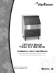
Manitowoc QF0400 Model Flake Ice Machine Installation, Use & Care Manual This manual is updated as new information and models are released. Visit our website for the latest manual. www.manitowocice.
Safety Notices Read These Before Proceeding: As you work on Manitowoc equipment, be sure to pay close attention to the safety notices in this manual. Disregarding the notices may lead to serious injury and/ or damage to the equipment. Throughout this manual, you will see the following types of safety notices: ! Warning Text in a Warning box alerts you to a potential personal injury situation. Be sure to read the Warning statement before proceeding, and work carefully.
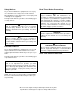
Table of Contents Section 1 General Information Model Numbers . . . . . . . . . . . . . . . . . . . . . . . . . . . . . . . . . . . . . . . . . . . . . . . . . . How to Read a Model Number . . . . . . . . . . . . . . . . . . . . . . . . . . . . . . . . . . . . . . Accessories . . . . . . . . . . . . . . . . . . . . . . . . . . . . . . . . . . . . . . . . . . . . . . . . . . Bin Caster . . . . . . . . . . . . . . . . . . . . . . . . . . . . . . . . . . . . . . . . . . . . . . . . . . .
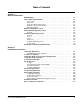
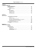
Table of Contents (continued) Section 3 Ice Machine Operation Component Identification . . . . . . . . . . . . . . . . . . . . . . . . . . . . . . . . . . . . . . . . . . Operational Checks . . . . . . . . . . . . . . . . . . . . . . . . . . . . . . . . . . . . . . . . . . . . . . General . . . . . . . . . . . . . . . . . . . . . . . . . . . . . . . . . . . . . . . . . . . . . . . . . . . . . Water Level Check . . . . . . . . . . . . . . . . . . . . . . . . . . . . . . . . . . . . . . . . . . . . QF0406A .
Section 1 General Information Model Numbers Accessories This manual covers the following models: BIN CASTER QF0406A Undercounter Self-Contained Air-Cooled Flake Ice Replaces standard legs. QF0406A ARCTIC PURE WATER FILTER SYSTEM ! Warning Do not operate equipment that has been misused, abused, neglected, damaged, or altered/modified from that of original manufactured specifications.
General Information Section 1 Model/Serial Number Location These numbers are required when requesting information from your local Manitowoc distributor, service representative, or Manitowoc Foodservice Record the model and serial number of your ice machine in the space provided below. The model and serial number are listed on the OWNER WARRANTY REGISTRATION CARD. They are also listed on the MODEL/SERIAL NUMBER DECAL affixed to the ice machine.
Section 1 General Information Flake/Chiplet/Nugget Commercial Ice Machine Warranty Manitowoc Ice, Inc.
General Information Section 1 Residential Ice Machine Limited Warranty WHAT DOES THIS LIMITED WARRANTY COVER? Subject to the exclusions and limitations below, Manitowoc Foodservice (“Manitowoc”) warrants to the original consumer that any new ice machine manufactured by Manitowoc (the “Product”) shall be free of defects in material or workmanship for the warranty period outlined below under normal use and maintenance, and upon proper installation and start-up in accordance with the instruction manual suppl
Section 2 Installation Instructions Ice Machine Dimensions Location of Ice Machine These instructions are provided to assist the qualified installer. Check your local Yellow Pages for the name of the nearest Manitowoc distributor, or call Manitowoc Foodservice for information regarding start-up services. The location selected for the ice machine must meet the following criteria. If any of these criteria are not met, select another location.
Installation Instructions Section 2 Ice Machine Head Section Clearance Requirements QF0406A Top/Sides Back Self-Contained Air-Cooled 5” (12.7 mm) 5” (12.7 mm) Self-Contained Water-Cooled NA NA Leveling the Ice Machine 1. Screw the leveling legs onto the bottom of the ice machine. 2. Screw the foot of each leg in as far as possible. ! Caution The legs must be screwed in tightly to prevent them from bending.
Section 2 Installation Instructions Electrical Service ! Warning All wiring must conform to local, state and national codes. QF0406A 115/60/1 ice machines are factory pre-wired with a power cord and 5-15P plug confirmation. QF0406A 230/50/1 ice machines are factory pre-wired with a power cord, no plug is supplied. VOLTAGE The maximum allowable voltage variation is ±10% of the rated voltage on the ice machine model/serial number plate at start-up (when the electrical load is highest).
Installation Instructions Section 2 Water Supply and Drains POTABLE WATER SUPPLY DRAIN CONNECTIONS Local water conditions may require treatment of the water to inhibit scale formation, filter sediment, and remove chlorine odor and taste. Follow these guidelines when installing drain lines to prevent drain water from flowing back into the ice machine and storage bin: POTABLE WATER INLET LINES • Drain lines must have a 1.5 inch drop per 5 feet of run (2.5 cm per meter), and must not create traps.
Section 2 Installation Instructions Installation Checklist Before Starting the Ice Machine X Installation Checklist Items Is the Ice Machine level? Has all of the internal packing been removed? Have all of the electrical and water connections been made? Has the supply voltage been tested and checked against the rating on the nameplate? Is there proper clearance around the ice machine for air circulation? Has the ice machine been installed where ambient temperatures will remain in the range of 45° 110°F
Installation Instructions Section 2 THIS PAGE INTENTIONALLY LEFT BLANK 2-6 Part Number 000005546 12/09
Section 3 Ice Machine Operation Component Identification QF0406A WATER FLOAT VALVE COIL WATER LEVEL PROBES EVAPORATOR WATER INLET QUICK DISCONNECT ICE CHUTE CONTROL BOX DUMP VALVE POTABLE WATER DRAIN ICE/OFF/CLEAN TOGGLE SWITCH CONDENSER FAN/ MOTOR Part Number 000005546 12/09 GEAR MOTOR / GEAR BOX ASSEMBLY SV2053 AIR COOLED CONDENSER SV2044 3-1
Ice Machine Operation Section 3 Operational Checks GENERAL WATER LEVEL CHECK Manitowoc ice machines are factory-operated and adjusted before shipment. Normally, a newly installed ice machine does not require any adjustment. The float valve maintains the correct water level. The water level must allow the water level probes to maintain water contact throughout the freeze cycle. The water level is factory set and normally will not require adjustment. Check the water level during the freeze cycle.
Section 3 Ice Machine Operation QF0406A PRIOR TO START-UP AUTOMATIC SHUT-OFF When the toggle switch is placed in the “ice” position the following must occur prior to starting an ice making cycle. 3. Ice Run Out A. The bin level probe must be open (bin level light off). If the probe is closed, (bin level light on) when the toggle switch is moved to ICE, the control system waits until the bin level probe opens, (bin level light off) before starting an ice making sequence.
Ice Machine Operation Section 3 THIS PAGE INTENTIONALLY LEFT BLANK 3-4 Part Number 000005546 12/09
Section 4 Maintenance Interior Cleaning and Sanitizing GENERAL You are responsible for maintaining the ice machine in accordance with the instructions in this manual. Maintenance procedures are not covered by the warranty. Clean and sanitize the ice machine every six months for efficient operation. If the ice machine requires more frequent cleaning and sanitizing, consult a qualified service company to test the water quality and recommend appropriate water treatment.
Maintenance Section 4 MANITOWOC’S CLEANING TECHNOLOGY Manitowoc Flake Ice Machines include technology that allows the initiation and completion of a cleaning or sanitizing cycle at the flip of a switch. This cycle will permit cleaning of all surfaces that come in contact with the water distribution system. Periodic maintenance must be performed that includes sanitizing the bin and adjacent surface areas, which are not contacted by the water distribution system.
Section 4 Maintenance CLEANING/SANITIZING PROCEDURE Use Ice machine cleaner part number 000000084. Use Ice machine sanitizer part number 94-0565-3. Step 1 Set the toggle switch to the OFF position and remove all ice from the bin. Step 2 Remove the 2 thumbscrews and white plastic panel. Step 3 Disconnect water supply line at float valve quick disconnect by depressing stainless steel lever (refer to disassembly for cleaning for procedure). Step 4 Follow the chart and premix cleaner and water.
Maintenance Section 4 PROCEDURE TO CLEAN HEAVILY SCALED FLAKE ICE MACHINES Step 1 Set the toggle switch to the OFF position and remove all ice from the bin. Step 2 Remove the 2 thumbscrews and white plastic panel from the interior back wall of the bin. Step 3 Disconnect water supply line at float valve quick disconnect by depressing stainless steel lever. Step 4 Refer to chart below: Premix cleaner with lukewarm water in a nonmetallic container.
Section 4 Maintenance REMOVAL OF PARTS FOR CLEANING/SANITIZING Inner Panel & Ice Diverter Removal ! Warning 1. Place the toggle switch in the OFF position, turn off the water supply and disconnect electrical power to the ice machine. Disconnect electric power to the ice machine at the electric switch box before proceeding. 2. Open bin door to access panel and diverter. 3. Remove thumbscrews and lift inner panel forward.
Maintenance Section 4 Float Valve Removal Water Level Probe Removal 1. Place the toggle switch in the OFF position, turn off the water supply and disconnect electrical power to the ice machine. 2. Disconnect water supply line at float valve quick disconnect by depressing stainless steel lever. 1. Place the toggle switch in the OFF position, turn off the water supply and disconnect electrical power to the ice machine. 3. Pull up on water level probes to remove. 2.
Section 4 Maintenance Cabinet Removal Bin Door Removal Door removal allows easier access for cleaning and sanitizing. 1. Remove all ice from bin and disconnect power and water supplies. 1. Disconnect the electrical power to the ice machine and remove ice from bin. 2. Remove thumbscrews and evaporator panel. 2. Grasp the rear of the bin door and pull bin door forward approximately 5”. 4. Remove three screws from the bottom of the left and right side of cabinet. 3.
Maintenance Section 4 Water Dump Valve The water dump valve normally does not require removal for cleaning. To determine if removal is necessary: 1. Locate the water dump valve. 2. Set the toggle switch to ICE. 3. While the ice machine is in the freeze mode, check the water trough to determine if the dump valve is leaking. If there is no or little water in the water trough (during the freeze cycle) the dump valve is leaking.
Section 4 Maintenance CLEANING THE CONDENSER ! Warning Disconnect electric power to the ice machine and the remote condenser at the electric service switch before cleaning the condenser. Air-Cooled Condenser A dirty condenser restricts airflow, resulting in excessively high operating temperatures. This reduces ice production and shortens component life. Clean the condenser at least every six months. Follow the steps below. 3. Shine a flashlight through the condenser to check for dirt between the fins.
Maintenance Section 4 Removal from Service/Winterization GENERAL Special precautions must be taken if the ice machine head section is to be removed from service for an extended period of time or exposed to ambient temperatures of 32°F (0°C) or below. ! Caution If water is allowed to remain in the ice machine in freezing temperatures, severe damage to some components could result. Damage of this nature is not covered by the warranty. Follow the applicable procedure below. 1.
Section 5 Before Calling Service Checklist If a problem arises during operation of your ice machine, follow the checklist below before calling for service. Routine adjustments and maintenance procedures are not covered by the warranty. Problem Ice machine does not operate. Possible Cause No electrical power to the ice machine. Control Board fuse open ICE/OFF/CLEAN toggle switch set improperly. 8 minute lockout has not expired. Bin level sensor is disconnected or is contacting the ice.
Before Calling Service Section 5 Safeguard Feature In addition to standard safety controls, your Manitowoc ice machine features built-in SafeGuards. The ice machine will stop when conditions arise that would cause major component failure. RESET PROCEDURE SAFEGUARD INDICATOR LIGHTS 1. Move the ICE/OFF/CLEAN toggle switch to OFF and then back to ICE. During a SafeGuard Mode the corresponding light (disch temp, water level or speed) will flash continuously. A.
Section 5 SAFEGUARD MODES No Water During the Freeze cycle if the water level probe opens or remains open for more than 30 continuous seconds, the ice machine will de-energize the compressor and gear motor, continuously flash the water level light and initiate a 60 minute Standby Mode. Before Calling Service WATER LEVEL PROBE OPENS OR REMAINS OPEN FOR MORE THAN 30 CONTINUOUS SECONDS: The ice machine will start another 60-minute Standby Mode.
Before Calling Service Section 5 Gear Motor Speed Anytime the motor speed sensor detects the motor speed (rpm) is below the minimum range for 3 continuous seconds, the ice machine will: 1. De-energize the compressor and/or gear motor. 2. Continuously flash the Gear Motor Speed light. 3. Initiate a 60-minute Standby Mode. During the Standby Mode the Motor Speed Sensor light will flash to indicate a Standby Mode.
Section 5 Before Calling Service Temperature is Too High or Low 4. After 30 minutes of compressor run time, the ice machine will check the discharge line temperature. The temperature sensor (thermistor) is mounted on the compressor discharge line. The temperature sensor provides input to the control board. The control board monitors the temperature anytime the compressor is energized. Discharge line temperature normal: The ice machine continues to make ice.
Before Calling Service Section 5 THIS PAGE INTENTIONALLY LEFT BLANK 5-6 Part Number 000005546 12/09
© 2009 Manitowoc Continuing product improvements may necessitate change of specifications without notice. Part Number 000005546 12/09 Manitowoc Foodservice 2110 South 26th Street, P.O. Box 1720 Manitowoc, WI 54221-1720, USA Ph: 920-682-0161 Fax: 920-683-7589 Visit us online at: www.manitowocfsg.