Q Model QuietQube® Ice Machines with CVD® Technology Models Q0600C/Q0800C/Q1000C Installation and Owner/Operator Use and Care Manual Thank you for selecting a Manitowoc Ice Machine, the dependability leader in ice making equipment and related products. With proper installation, care and maintenance, your new Manitowoc Ice Machine will provide you with many years of reliable and economical performance.
Safety Notices Procedural Notices As you work on a QuietQube®-Series Ice Machine, be sure to pay close attention to the safety notices in this manual. Disregarding the notices may lead to serious injury and/or damage to the ice machine. As you work on a QuietQube®-Series Ice Machine, be sure to read the procedural notices in this manual. These notices supply helpful information which may assist you as you work.
Table of Contents Section 1 General Information Model Numbers . . . . . . . . . . . . . . . . . . . . . . . . . . . . . . . . . . . . . . . . . . . . . . . . . How to Read a Model Number . . . . . . . . . . . . . . . . . . . . . . . . . . . . . . . . . . . . . Remote Condensing Unit . . . . . . . . . . . . . . . . . . . . . . . . . . . . . . . . . . . . . . . . . Ice Cube Sizes . . . . . . . . . . . . . . . . . . . . . . . . . . . . . . . . . . . . . . . . . . . . . . . . . . Accessories . . . . . . . . .
Table of Contents (continued) Electrical Requirements . . . . . . . . . . . . . . . . . . . . . . . . . . . . . . . . . . . . . . . . . . . QuietQube® Ice Machine Head Section Electrical Wiring Connections . . . . QuietQube® Ice Machine Head Section 115/1/60 . . . . . . . . . . . . . . . . . . . . . . . . . . . . . . . . . . . . . . . . . . . . . . . . . . . . QuietQube® Ice Machine Head Section 230/1/50 . . . . . . . . . . . . . . . . . . . . . . . . . . . . . . . . . . . . . . . . . . . . . . . . . . . .
Table of Contents (continued) Section 4 Maintenance General . . . . . . . . . . . . . . . . . . . . . . . . . . . . . . . . . . . . . . . . . . . . . . . . . . . . . . . . Ice Machine Inspection . . . . . . . . . . . . . . . . . . . . . . . . . . . . . . . . . . . . . . . . . . . Exterior Cleaning . . . . . . . . . . . . . . . . . . . . . . . . . . . . . . . . . . . . . . . . . . . . . . . . Cleaning the Condenser . . . . . . . . . . . . . . . . . . . . . . . . . . . . . . . . . . . . . . . . . . General .
Table of Contents (continued) 4 Part No.
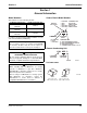
Section 1 General Information Section 1 General Information Model Numbers How to Read a Model Number This manual covers the following models: Ice Machine Head Section QD0672C QY0674C QD0872C QY0874C QD1072C QY1074C CVD® Condensing Unit* 9 REMOTE AIR-COOLED CVD675 # CUBE SIZE CONDENSER TYPE 2 3 4 5 AIR-COOLED WATER-COOLED AIR-COOLED WATER-COOLED DICE DICE HALF-DICE HALF-DICE CVD875 Q Y 0674 C CVD1075 For 3 phase electrical option: add the number “3” to the end of model number (CVD10753).
General Information Section 1 Accessories Contact your Manitowoc distributor for these optional accessories: BIN CASTER WATER FILTER SYSTEM Replaces standard legs. Engineered specifically for Manitowoc ice machines, This water filter is an efficient, dependable, and affordable method of inhibiting scale formation, filtering sediment, and removing chlorine taste and odor.
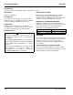
Section 1 General Information Model/Serial Number Location Record the model and serial number of your ice machine and bin or dispenser in the space provided below. These numbers are required when requesting information from your local Manitowoc distributor, service representative, or Manitowoc Ice, Inc. The model and serial number are listed on the OWNER WARRANTY REGISTRATION CARD. They are also listed on the MODEL/SERIAL NUMBER DECAL affixed to the ice machine head section and condensing unit.
General Information Section 1 Owner Warranty Registration Card EXCLUSIONS GENERAL The following items are not included in the ice machine’s warranty coverage: The packet containing this manual also includes warranty information. Warranty coverage begins the day the ice machine is installed. Important Complete and mail the OWNER WARRANTY REGISTRATION CARD as soon as possible to validate the installation date.
Section 2 Installation Instructions Section 2 Installation Instructions General These instructions are provided to assist the qualified installer. Check your local Yellow Pages for the name of the nearest Manitowoc distributor, or call Manitowoc Ice, Inc. for information regarding installation and start-up services. Important Failure to follow these installation guidelines may affect warranty coverage.
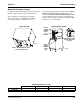
Installation Instructions Section 2 Ice Machine Dimensions CVD Condensing Unit Dimensions Q0600C/Q0800C/Q1000C ICE MACHINES CVD0675/CVD0875/CVD1075 Important Failure to follow these installation guidelines may affect warranty coverage. 24.5” (62.23 CM) 30” (76.2 CM) 24.13” (53.7 CM) 34” (86.4 CM) 13” (33 CM) H 25.75” (65.4 CM) 8” (20.3 CM) 22” (56 CM) 4.5” (11.4 CM) 2.13” (5.4 CM) SV1752 5.5” (14 CM) 14.5” (36.8 CM) 14.5” (36.8 CM) 5.13” (13.03 CM) 9.5” (24.
Section 2 Installation Instructions Ice Storage Bin Dimensions S170/S400/S570 ICE STORAGE BIN S970 ICE STORAGE BINS SV1609 Bin Model S170 S400 S570 Dimension A 29.5 in (74.9 cm) 34.0 in (86.3 cm) 34.0 in (86.3 cm) Dimension B 19.1 in (48.5 cm) 32.0 in (81.3 cm) 44.0 in (111.7 cm) SV1610 ! Warning Manitowoc QuietQube ice machines require the ice storage (bin, dispenser, etc.) to incorporate an ice deflector.
Installation Instructions Section 2 Location of Ice Machine Location of CVD Condensing Unit The location selected for the ice machine must meet the following criteria. If any of these criteria are not met, select another location. The location selected for the CVD Condensing Unit must meet the following criteria. If any of these criteria are not met, select another location. • The location must be free of airborne and other contaminants. • The air temperature must be at least -20°F (-28.
Section 2 Installation Instructions Leveling the Ice Storage Bin Air-Cooled Baffle 1. Screw the leveling legs onto the bottom of the bin. 2. Screw the foot of each leg in as far as possible. The air-cooled baffle prevents condenser air from recirculating. To install: 1. Remove the back panel screws next to the condenser. ! Caution The legs must be screwed in tightly to prevent them from bending. 2. Align the mounting holes in the air baffle with the screw holes and reinstall the screws. 3.
Installation Instructions Section 2 Electrical Service FUSE/CIRCUIT BREAKER GENERAL The ice machine head section and condensing unit are wired independently from each other. ! Warning All wiring must conform to local, state and national codes. The ice machine head section does not require a dedicated circuit breaker.
Section 2 Installation Instructions Electrical Requirements QuietQube® Ice Machine Head Section Ice Machine Q0670C Q0870C Q1070C Voltage Phase Cycle Maximum Fuse/ Circuit Breaker Total Amps 115/1/60 208-230/1/60 230/1/50 115/1/60 208-230/1/60 230/1/50 115/1/60 208-230/1/60 230/1/50 15 amp 15 amp 15 amp 15 amp 15 amp 15 amp 15 amp 15 amp 15 amp 1.1 0.6 0.6 1.1 0.6 0.6 1.1 0.6 0.6 Important The QuietQube® Ice Machine Head Section and CVD Condensing Unit are wired independently from each other.
Installation Instructions Section 2 QuietQube® Ice Machine Head Section Electrical Wiring Connections ! Warning These diagrams are not intended to show proper wire routing, wire sizing, disconnects, etc., only the correct wire connections. All electrical work, including wire routing and grounding, must conform to local, state and national electrical codes. Though wire nuts are shown in the drawings, the ice machine field wiring connections may use either wire nuts or screw terminals.
Section 2 Installation Instructions Condensing Unit Wiring Connections CVD CONDENSING UNIT 208-230/3/60 ! Warning These diagrams are not intended to show proper wire routing, wire sizing, disconnects, etc., only the correct wire connections. All electrical work, including wire routing and grounding, must conform to local, state and national electrical codes. Though wire nuts are shown in the drawings, the ice machine field wiring connections may use either wire nuts or screw terminals.
Installation Instructions Section 2 Ice Machine Head Section Water Supply and Drains POTABLE WATER SUPPLY DRAIN CONNECTIONS Local water conditions may require treatment of the water to inhibit scale formation, filter sediment, and remove chlorine odor and taste.
Section 2 Installation Instructions WATER SUPPLY AND DRAIN LINE SIZING/CONNECTIONS ! Caution Plumbing must conform to state and local codes. Location Water Temperature Water Pressure Ice Machine Fitting Ice Making Water Inlet 33°F (0.6°C) Min. 90°F (32.2°C) Max. --- 20 psi (137.9 kPA) Min. 80 psi (551.5 kPA) Max. --- 3/8” Female Pipe Thread Tubing Size Up to Ice Machine Fitting 3/8” (9.5 mm) min. inside diameter --- --- 1/2” Female Pipe Thread 3/4” Female Pipe Thread 1/2” (12.7 mm) min.
Installation Instructions Section 2 Refrigeration System Installation QuietQube® Ice Machine Remote Single Circuit Condenser Q0670C Q0870C CVD675 CVD875 Q1070C CVD1075 Factory Equipment Refrigeration Amounts ICE MACHINE HEAD SECTION Line Set* RC-21 RC-31 RC-51 RC-20 RC-30 RC-50 *Line Set Suction Line Liquid Line Insulation Thickness RC 20/30/50 3/4 inch (19.1 mm) 5/8 inch (15.9 mm) 1/2 inch (12.7 mm) 3/8 inch (9.
Section 2 Installation Instructions Refrigeration Line Set Installation A. LINE SET LENGTH GENERAL 100 feet (30.5 m) Length: The maximum measured length the line set can be. Refrigeration line set installations consist of vertical and horizontal line set distances between the ice machine and the condensing unit. The following guidelines, drawings and calculation methods must be followed to assure proper oil return and CVD® condensing unit/ice machine operation.
Installation Instructions Section 2 C. SUCTION LINE OIL TRAPS ! Caution Do not form unwanted traps in refrigeration lines. Never coil excess refrigeration tubing. 0 to 20 feet (0 to 6.1 m) Rise: The ice machine head section has one oil trap built in which allows for a maximum condenser rise of 20 feet (6.1 m) without additional traps in the suction line. 21 to 35 feet (6.4 to 10.7 m) Rise: The suction line requires an additional Oil Trap (“S” type) to be installed.
Section 2 Installation Instructions Step 4 Connecting the line set. Connect The Line Set To The CVD Condensing Unit To prevent oxidation of the copper, purge line set and condensing unit with dry nitrogen while brazing. ! Warning The condensing unit ships from the factory pressurized with a 50/50 mixture of nitrogen/helium. Bleed off pressure from both suction and liquid line access ports prior to cutting into refrigeration lines.
Installation Instructions Section 2 Step 5 Pressure Test and Evacuate The Line Set and CVD Condensing Unit Schrader valve core removal tools that allow for removal and installation of the valve cores without removing manifold gauge set hoses are recommended to decrease the evacuation time. Leave the line set shut off valves closed (front seated). Pressure test the line sets and CVD condensing unit with 150 psig of dry nitrogen.
Section 2 Installation Instructions Step 6 Open The Valves Prior To Starting The Ice Machine. A. Slowly backseat (open-turn counterclockwise) the suction line shut off valve. B. Slowly backseat (open-turn counterclockwise) the liquid line shut off valve. C. Slowly backseat (open-turn counterclockwise) the receiver service valve. NOTE: You will not hear refrigerant flow when the valves are opened.
Installation Instructions Section 2 Step 7 Leak Check The Refrigeration System Leak check the new line set connections at the ice machine head section, condensing unit and S trap as well as all factory joints throughout the entire system. Disconnect power to the CVD condensing unit. Place the ICE/OFF/CLEAN toggle switch into the ICE position. This allows the low side and high side pressures to equalize. Place the ICE/OFF/CLEAN toggle switch in the OFF position.
Section 2 Installation Instructions CVD CONDENSING UNIT ELECTRICAL DISCONNECT SUCTION LINE LIQUID LINE ELECTRICAL DISCONNECT ICE MACHINE HEAD SECTION SUCTION REFRIGERANT SHUT-OFF VALVE ELECTRICAL SUPPLY LIQUID REFRIGERANT SHUT-OFF VALVE BIN SV1759 Typical QuietQube® System Installation Part No.
Installation Instructions Section 2 Installation Checklist Is the Ice Machine level? Has the sump trough plug been installed? Has all of the internal packing been removed? Has the ice machine receiver service valve been opened? Have all of the electrical and water connections been made? Has the supply voltage been tested and checked against the rating on the nameplate? Does the condenser fan motor(s) operate properly after start-up? Have all the refrigeration fittings and joints been leak checked? I
Section 2 Installation Instructions Before Starting the Ice Machine AuCS® Automatic Cleaning System All Manitowoc ice machines are factory-operated and adjusted before shipment. Normally, new installations do not require any adjustment. To ensure proper operation, follow the Operational Checks in Section 3 of this manual. Starting the ice machine and completing the Operational Checks are the responsibilities of the owner/operator.
Installation Instructions Section 2 THIS PAGE INTENTIONALLY LEFT BLANK 2-22 Part No.
Section 3 Ice Machine Operation Section 3 Ice Machine Operation Component Identification ICE MACHINE HEAD SECTION Q0600C/Q0800C/Q1000C COOL VAPOR VALVE LIQUID LINE SOLENOID VALVE WATER INLET VALVE DISTRIBUTION TUBE EVAPORATOR ICE THICKNESS PROBE WATER LEVEL PROBE RECEIVER SERVICE VALVE RECEIVER SUCTION LINE SHUT-OFF VALVE WATER DUMP VALVE WATER PUMP WATER CURTAIN LIQUID LINE SHUT-OFF VALVE DRAIN HOSE ICE/OFF.
Ice Machine Operation Section 3 Ice Making Sequence of Operation INITIAL START-UP OR START-UP AFTER AUTOMATIC SHUT-OFF 1. Water Purge Before the compressor starts, the water pump and water dump solenoid are energized for 45 seconds, to completely purge the ice machine of old water. This feature ensures that the ice making cycle starts with fresh water.
Section 3 Ice Machine Operation HARVEST SEQUENCE AUTOMATIC SHUT-OFF 5. Water Purge 7. Automatic Shut-Off The water pump continues to run, and the water dump valve energizes for 45 seconds to purge the water in the sump trough. The water fill valve energizes (turns on) for the last 15 seconds of the 45-second water purge. Ice Machine Section: When the storage bin is full at the end of a harvest sequence, the sheet of cubes fails to clear the water curtain and will hold it open.
Ice Machine Operation Section 3 Operational Checks ICE THICKNESS CHECK GENERAL After a harvest cycle, inspect the ice cubes in the ice storage bin. The ice thickness probe is factory-set to maintain the ice bridge thickness at 1/8" (3.2 mm). Manitowoc ice machines are factory-operated and adjusted before shipment. Normally, a newly installed ice machine does not require any adjustment.
Section 3 Ice Machine Operation HARVEST SEQUENCE WATER PURGE The harvest sequence water purge adjustment may only be used when the ice machine is hooked up to special water systems, such as a de-ionized water treatment system. ! Warning Disconnect the electrical power to the ice machine at the electrical disconnect before proceeding. Important The harvest sequence water purge is factory-set at 45 seconds. A shorter purge setting (with standard water supplies such as city water) is not recommended.
Ice Machine Operation Section 3 THIS PAGE INTENTIONALLY LEFT BLANK 3-6 Part No.
Section 4 Maintenance Section 4 Maintenance General Ice Machine Inspection You are responsible for maintaining the ice machine in accordance with the instructions in this manual. Maintenance procedures are not covered by the warranty. ! Warning Disconnect electric power to the ice machine and the CVD condensing unit at the electric service switch before cleaning the condenser.
Maintenance Section 4 Cleaning the Condenser 3. Straighten any bent condenser fins with a fin comb. GENERAL “COMB” DOWN ONLY ! Warning Disconnect electric power to the ice machine head section and the CVD condensing unit at the electric service switches before cleaning the condenser. CONDENSER A dirty condenser restricts airflow, resulting in excessively high operating temperatures. This reduces ice production and shortens component life. Clean the condenser at least every six months.
Section 4 Maintenance Interior Cleaning and Sanitizing Clean and sanitize the ice machine every six months for efficient operation. If the ice machine requires more frequent cleaning and sanitizing, consult a qualified service company to test the water quality and recommend appropriate water treatment or installation of AuCS accessory (Automatic Cleaning System). If required, an extremely dirty ice machine may be taken apart for cleaning and sanitizing.
Maintenance Section 4 CLEANING PROCEDURE Ice machine cleaner is used to remove lime scale or other mineral deposits. It is not used to remove algae or slime. Refer to the “Sanitizing Procedure” for removal of algae and slime. To initiate a cleaning cycle using Manitowoc’s Patented Cleaning Technology use the following procedure. Step 1 Set the toggle switch to the OFF position after ice falls from the evaporator at the end of a Harvest cycle.
Section 4 Maintenance SANITIZING PROCEDURE Step 7 Use sanitizer to remove algae or slime. Do not use it to remove lime scale or other mineral deposits. To initiate a sanitizing cycle using Manitowoc’s Patented Cleaning/ Sanitizing Technology use the following procedure. Step 1 Set the toggle switch to the OFF position after ice falls from the evaporator at the end of a Harvest cycle. Or, set the switch to the OFF position and allow the ice to melt off the evaporator.
Maintenance Section 4 AUTOMATIC CLEANING SYSTEM (AuCS) This accessory monitors ice making cycles and initiates cleaning (or sanitizing) procedures automatically. The AuCS Accessory can be set to automatically clean or sanitize the ice machine every 2, 4, or 12 weeks. Periodic maintenance must be performed that includes cleaning of sanitizing the bin (or dispenser) and adjacent surface areas, which cannot be contacted by the water distribution system.
Section 4 Maintenance REMOVAL OF PARTS FOR CLEANING/SANITIZING 4. Use a soft-bristle brush or sponge (NOT a wire brush) to carefully clean the parts. ! Warning Disconnect electric power to the ice machine at the electric switch box before proceeding. ! Warning Wear rubber gloves and safety goggles (and/or face shield) when handling Ice Machine Cleaner or Sanitizer. ! Caution Do not mix Cleaner and Sanitizer solutions together.
Maintenance Section 4 Water Dump Valve The water dump valve normally does not require removal for cleaning. To determine if removal is necessary: 1. Locate the water dump valve. 2. Set the toggle switch to ICE. 3. While the ice machine is in the freeze mode, check the dump valve’s clear plastic outlet drain hose for leakage. • If the dump valve is leaking, remove, disassemble and clean it. • If the dump valve is not leaking, do not remove it. Instead, follow the “Cleaning Procedure”.
Section 4 Maintenance Water Curtain Ice Thickness Probe 1. Gently flex the curtain in the center and remove it from the right side. 1. Compress the side of the ice thickness probe near the top hinge pin and remove it from the bracket. DISCONNECT WIRE LEAD STEP 1 COMPRESS HINGE PIN TO REMOVE STEP 2 SV1213 Water Curtain Removal ICE THICKNESS PROBE SV1591 2. Slide the left pin out. Ice Thickness Probe Removal NOTE: At this point, the ice thickness probe can easily be cleaned.
Maintenance Section 4 Water Pump Water Distribution Tube ! Warning ! Warning Disconnect the electric power to the ice machine at the electric service switch box and turn off the water supply. 1. Disconnect the water pump power cord. Disconnect the electrical power to the ice machine at the electrical disconnect before proceeding. 1. Remove the clamp from the vinyl water hose on the right side of the distribution tube. LOOSEN SCREWS WATER PUMP 2 3 1. LIFT UP 2. SLIDE BACK 3.
Section 4 Maintenance Water Level Probe Water Inlet Valve 1. Loosen the screw that holds the water level probe in place. The probe can easily be cleaned at this point without proceeding to step 2. ! Warning Disconnect the electrical power to the ice machine at the electrical disconnect before proceeding. 2. If complete removal is required, disconnect the wire lead from the control board inside the electrical control box. SCREW 1. Set the ICE/OFF/CLEAN switch to OFF.
Maintenance Section 4 Removal from Service/Winterization GENERAL Special precautions must be taken if the ice machine head section is to be removed from service for an extended period of time or exposed to ambient temperatures of 32°F (0°C) or below. ! Caution If water is allowed to remain in the ice machine in freezing temperatures, severe damage to some components could result. Damage of this nature is not covered by the warranty. Follow the applicable procedure below. 1.
Section 5 Before Calling For Service Section 5 Before Calling For Service Checklist If a problem arises during operation of your ice machine, follow the checklist below before calling service. Routine adjustments and maintenance procedures are not covered by the warranty. Problem Ice machine does not operate. Ice machine stops, and can be restarted by moving the toggle switch to OFF and back to ICE. Ice machine does not release ice or is slow to harvest. Ice machine does not cycle into harvest mode.
Before Calling For Service Problem Ice machine produces shallow or incomplete cubes, or the ice fill pattern on the evaporator is incomplete. Section 5 Possible Cause Ice thickness probe is out of adjustment. Water trough level is too high or too low. Water inlet valve filter screen is dirty. Water filtration is poor. Hot incoming water. Water inlet valve is not working. Incorrect incoming water pressure. Ice machine head section is not level. Low ice capacity. Water inlet valve filter screen is dirty.
MANITOWOC ICE, INC. 2110 South 26th Street P.O. Box 1720 Manitowoc, WI 54221-1720 Phone: (920) 682-0161 Service Fax: (920) 683-7585 Web Site - www.manitowocice.com © 2003 Manitowoc Ice, Inc. Litho in U.S.A.