
Specifications


Table Of Contents
- Q_Model_TOC_uc.pdf
- Model Numbers 1-1
- How to Read a Model Number 1-1
- Ice Cube Sizes 1-1
- Accessories 1-2
- Model/Serial Number Location 1-3
- Warranty 1-4
- Warranty Coverage 1-4
- General 2-1
- Ice Machine Dimensions 2-1
- Ice Storage Bin Dimensions 2-3
- Remote Condenser Dimensions 2-4
- Location of Ice Machine 2-5
- Stacking Two Ice Machines on a Single Storage Bin 2-5
- Ice Machine Heat of Rejection 2-5
- Leveling the Ice Storage Bin 2-6
- Air-Cooled Baffle 2-6
- Electrical Service 2-7
- Self-Contained Electrical Wiring Connections 2-9
- For United Kingdom Only 2-9
- Remote Electrical Wiring Connections 2-10
- Water Supply and Drain Requirements 2-11
- Cooling Tower Applications (Water-Cooled Models) 2-11
- Remote Condenser/Line Set Installation 2-13
- Remote Ice Machine Usage with Non-Manitowoc Multi-Circuit Condensers 2-17
- Installation Check List 2-19
- Additional Checks for Remote Models 2-19
- Before Starting the Ice Machine 2-20
- AuCS® Automatic Cleaning System 2-20
- Component Identification 3-1
- Ice Machine Sequence of Operation Q200/Q280/Q320/Q370/Q420/Q450/Q600/Q800/Q1000/Q1300/Q1600/Q1800 3-2
- Remote Q450/Q600/Q800/Q1000/Q1300/Q1600/Q1800 3-4
- Operational Checks 3-6
- General 4-1
- Ice Machine Inspection 4-1
- Exterior Cleaning 4-1
- Cleaning the Condenser 4-2
- Interior Cleaning and Sanitizing 4-4
- Removal from Service/Winterization 4-12
- Checklist 5-1
- Safety Limit Feature 5-2
- Q_Model_Section_1_uc.pdf
- Q_Model_Section_2_uc.pdf
- Section 2 Installation Instructions
- General
- Ice Machine Dimensions
- Ice Storage Bin Dimensions
- Remote Condenser Dimensions
- Location of Ice Machine
- Stacking Two Ice Machines on a Single Storage Bin
- Ice Machine Heat of Rejection
- Leveling the Ice Storage Bin
- Air-Cooled Baffle
- Electrical Service
- Self-Contained Electrical Wiring Connections
- For United Kingdom Only
- Remote Electrical Wiring Connections
- Water Supply and Drain Requirements
- Cooling Tower Applications (Water-Cooled Models)
- Remote Condenser/Line Set Installation
- Remote Ice Machine Usage with Non-Manitowoc Multi-Circuit Condensers
- Installation Check List
- Additional Checks for Remote Models
- Before Starting the Ice Machine
- AuCS® Automatic Cleaning System
- Section 2 Installation Instructions
- Q_Model_Section_3_uc.pdf
- Q_Model_Section_5_uc.pdf
Installation Instructions Section 2
2-18
Part No. 80-1375-3
NON-MANITOWOC MULTI-CIRCUIT CONDENSER SIZING CHART
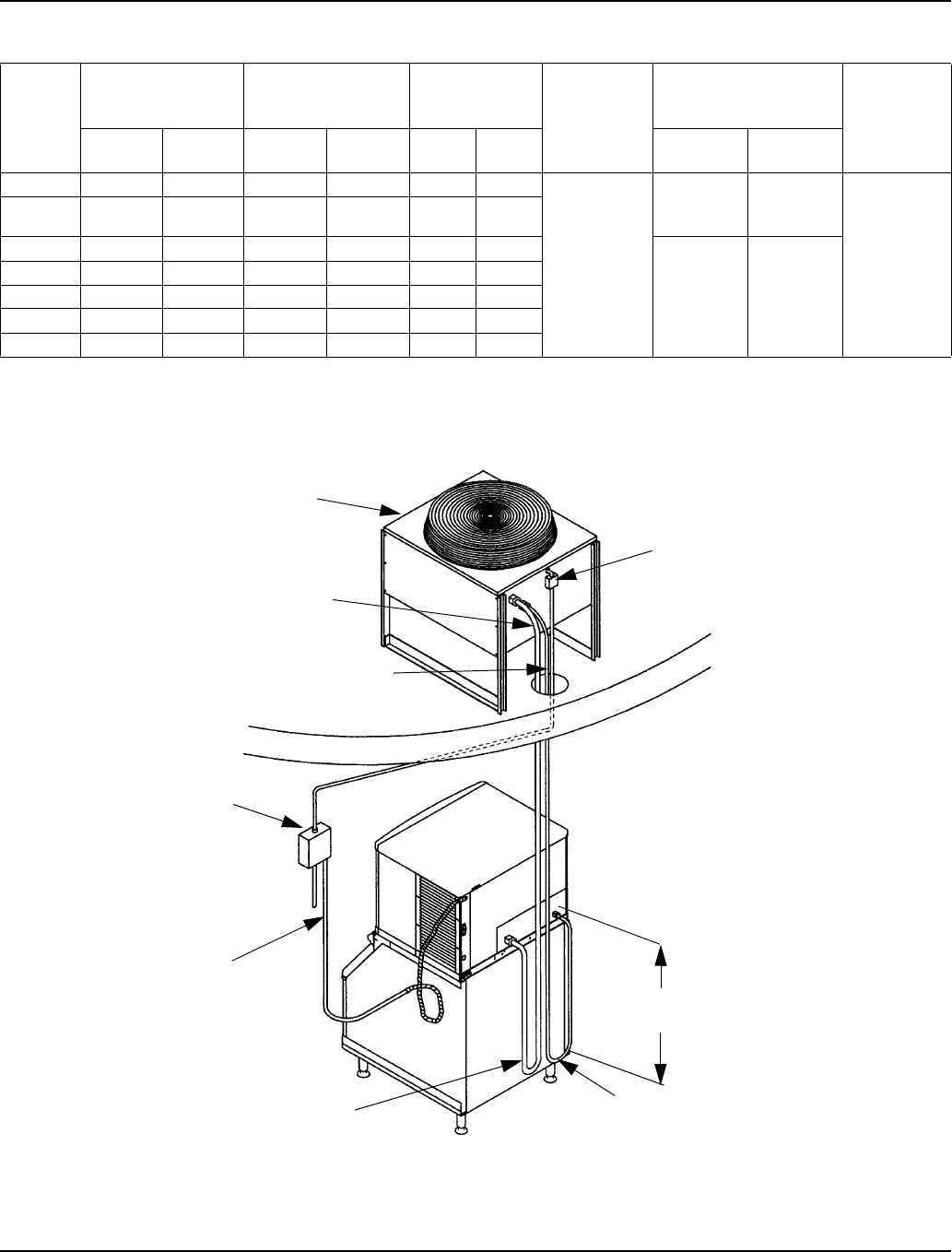
Typical Single Circuit Remote Condenser Installation
Ice
Machine
Model
Refrigerant Heat of Rejection
Internal
Condenser
Volume (cu ft)
Design
Pressure
Quick Connect Stubs-
Male Ends
Head
Pressure
Control
Valve
Type Charge
Average
Btu/hr
Peak
Btu/hr
Min Max Discharge Liquid
Q450 R-404A 6 lbs. 7,000 9,600 0.020 0.035 500 psig
safe working
pressure
coupling
P/N
83-6035-3
coupling
P/N
83-6034-3
Manitowoc
P/N
83-6809-3
Q600 R-404A 8 lbs. 9,000 13,900 0.045 0.060
Q800 R-404A 8 lbs. 12,400 19,500 0.045 0.060
2,500 psig
burst
pressure
mounting
flange P/N
83-6006-3
mounting
flange P/N
83-6005-3
no
substitutes
Q1000 R-404A 9.5 lbs. 16,000 24,700 0.065 0.085
Q1300 R-404A 14 lbs.
1
24,000 35,500 0.085 0.105
Q1600 R-404A 17 lbs.
1
36,000 50,000 0.130 0.170
Q1800 R-404A 17 lbs.
Amount reflects additional R-404A refrigerant added to nameplate charge for 50' to 100' line sets, to ensure proper operation at all ambient
conditions. Q1300 has 1.5 lbs. additional R-404A. Q1600 and Q1800 has 2.0 lbs. additional R-404A
36,000 50,000 0.130 0.170
SV1615
SINGLE CIRCUIT REMOTE
CONDENSER
ELECTRICAL
DISCONNECT
DISCHARGE
LINE
LIQUID LINE
ELECTRICAL
DISCONNECT
ELECTRICAL
SUPPLY
ICE MACHINE
BIN
DISCHARGE
REFRIGERANT
LINE
LIQUID
REFRIGERANT
LINE
36.00"
(91.44 cm)
DROP