
Specifications


Table Of Contents
- Q_Model_TOC_uc.pdf
- Model Numbers 1-1
- How to Read a Model Number 1-1
- Ice Cube Sizes 1-1
- Accessories 1-2
- Model/Serial Number Location 1-3
- Warranty 1-4
- Warranty Coverage 1-4
- General 2-1
- Ice Machine Dimensions 2-1
- Ice Storage Bin Dimensions 2-3
- Remote Condenser Dimensions 2-4
- Location of Ice Machine 2-5
- Stacking Two Ice Machines on a Single Storage Bin 2-5
- Ice Machine Heat of Rejection 2-5
- Leveling the Ice Storage Bin 2-6
- Air-Cooled Baffle 2-6
- Electrical Service 2-7
- Self-Contained Electrical Wiring Connections 2-9
- For United Kingdom Only 2-9
- Remote Electrical Wiring Connections 2-10
- Water Supply and Drain Requirements 2-11
- Cooling Tower Applications (Water-Cooled Models) 2-11
- Remote Condenser/Line Set Installation 2-13
- Remote Ice Machine Usage with Non-Manitowoc Multi-Circuit Condensers 2-17
- Installation Check List 2-19
- Additional Checks for Remote Models 2-19
- Before Starting the Ice Machine 2-20
- AuCS® Automatic Cleaning System 2-20
- Component Identification 3-1
- Ice Machine Sequence of Operation Q200/Q280/Q320/Q370/Q420/Q450/Q600/Q800/Q1000/Q1300/Q1600/Q1800 3-2
- Remote Q450/Q600/Q800/Q1000/Q1300/Q1600/Q1800 3-4
- Operational Checks 3-6
- General 4-1
- Ice Machine Inspection 4-1
- Exterior Cleaning 4-1
- Cleaning the Condenser 4-2
- Interior Cleaning and Sanitizing 4-4
- Removal from Service/Winterization 4-12
- Checklist 5-1
- Safety Limit Feature 5-2
- Q_Model_Section_1_uc.pdf
- Q_Model_Section_2_uc.pdf
- Section 2 Installation Instructions
- General
- Ice Machine Dimensions
- Ice Storage Bin Dimensions
- Remote Condenser Dimensions
- Location of Ice Machine
- Stacking Two Ice Machines on a Single Storage Bin
- Ice Machine Heat of Rejection
- Leveling the Ice Storage Bin
- Air-Cooled Baffle
- Electrical Service
- Self-Contained Electrical Wiring Connections
- For United Kingdom Only
- Remote Electrical Wiring Connections
- Water Supply and Drain Requirements
- Cooling Tower Applications (Water-Cooled Models)
- Remote Condenser/Line Set Installation
- Remote Ice Machine Usage with Non-Manitowoc Multi-Circuit Condensers
- Installation Check List
- Additional Checks for Remote Models
- Before Starting the Ice Machine
- AuCS® Automatic Cleaning System
- Section 2 Installation Instructions
- Q_Model_Section_3_uc.pdf
- Q_Model_Section_5_uc.pdf
Installation Instructions Section 2
2-16
Part No. 80-1375-3
LENGTHENING OR REDUCING LINE SET LENGTHS
In most cases, by routing the line set properly,
shortening will not be necessary. When shortening or
lengthening is required, do so before connecting the line
set to the ice machine or the remote condenser. This
prevents the loss of refrigerant in the ice machine or
condenser.
The quick connect fittings on the line sets are equipped
with Schraeder valves. Use these valves to recover any
vapor charge from the line set. When lengthening or
shortening lines, follow good refrigeration practices and
insulate new tubing. Do not change the tube sizes.
Evacuate the lines and place about 5 oz (143g) of vapor
refrigerant charge in each line.
CONNECTING A LINE SET
1. Remove the dust caps from the line set, condenser
and ice machine.
2. Apply refrigeration oil to the threads on the quick
disconnect couplers before connecting them to the
condenser.
3. Carefully thread the female fitting to the condenser
or ice machine by hand.
4. Tighten the couplings with a wrench until they
bottom out.
5. Turn an additional 1/4 turn to ensure proper brass-
to-brass seating. Torque to the following
specifications:
6. Check all fittings for leaks.
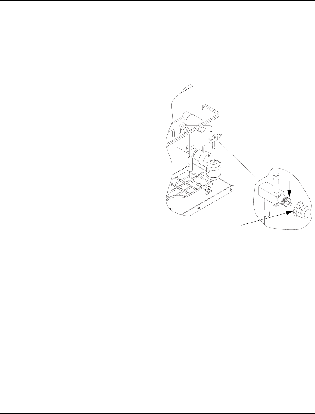
REMOTE RECEIVER SERVICE VALVE
The receiver service valve is closed during shipment.
Open the valve prior to starting the ice machine.
1. Remove the top and left side panels.
2. Remove the receiver service valve cap.
3. Backseat (open) the valve.
4. Reinstall the cap and panels.
Backseating the Receiver Service Valve
Liquid Line Discharge Line
10-12 ft lb.
(13.5-16.2 N•m)
35-45 ft lb.
(47.5-61.0 N•m)
SV1603
REMOVE FRONT, TOP,
AND LEFT SIDE PANEL
FOR ACCESS TO
RECEIVER VALVE
TURN
COUNTERCLOCKWISE TO
OPEN
RECEIVER SERVICE
VALVE CAP (TURN
COUNTERCLOCKWISE TO
REMOVE)