
Specifications


Table Of Contents
- Q_Model_TOC_uc.pdf
- Model Numbers 1-1
- How to Read a Model Number 1-1
- Ice Cube Sizes 1-1
- Accessories 1-2
- Model/Serial Number Location 1-3
- Warranty 1-4
- Warranty Coverage 1-4
- General 2-1
- Ice Machine Dimensions 2-1
- Ice Storage Bin Dimensions 2-3
- Remote Condenser Dimensions 2-4
- Location of Ice Machine 2-5
- Stacking Two Ice Machines on a Single Storage Bin 2-5
- Ice Machine Heat of Rejection 2-5
- Leveling the Ice Storage Bin 2-6
- Air-Cooled Baffle 2-6
- Electrical Service 2-7
- Self-Contained Electrical Wiring Connections 2-9
- For United Kingdom Only 2-9
- Remote Electrical Wiring Connections 2-10
- Water Supply and Drain Requirements 2-11
- Cooling Tower Applications (Water-Cooled Models) 2-11
- Remote Condenser/Line Set Installation 2-13
- Remote Ice Machine Usage with Non-Manitowoc Multi-Circuit Condensers 2-17
- Installation Check List 2-19
- Additional Checks for Remote Models 2-19
- Before Starting the Ice Machine 2-20
- AuCS® Automatic Cleaning System 2-20
- Component Identification 3-1
- Ice Machine Sequence of Operation Q200/Q280/Q320/Q370/Q420/Q450/Q600/Q800/Q1000/Q1300/Q1600/Q1800 3-2
- Remote Q450/Q600/Q800/Q1000/Q1300/Q1600/Q1800 3-4
- Operational Checks 3-6
- General 4-1
- Ice Machine Inspection 4-1
- Exterior Cleaning 4-1
- Cleaning the Condenser 4-2
- Interior Cleaning and Sanitizing 4-4
- Removal from Service/Winterization 4-12
- Checklist 5-1
- Safety Limit Feature 5-2
- Q_Model_Section_1_uc.pdf
- Q_Model_Section_2_uc.pdf
- Section 2 Installation Instructions
- General
- Ice Machine Dimensions
- Ice Storage Bin Dimensions
- Remote Condenser Dimensions
- Location of Ice Machine
- Stacking Two Ice Machines on a Single Storage Bin
- Ice Machine Heat of Rejection
- Leveling the Ice Storage Bin
- Air-Cooled Baffle
- Electrical Service
- Self-Contained Electrical Wiring Connections
- For United Kingdom Only
- Remote Electrical Wiring Connections
- Water Supply and Drain Requirements
- Cooling Tower Applications (Water-Cooled Models)
- Remote Condenser/Line Set Installation
- Remote Ice Machine Usage with Non-Manitowoc Multi-Circuit Condensers
- Installation Check List
- Additional Checks for Remote Models
- Before Starting the Ice Machine
- AuCS® Automatic Cleaning System
- Section 2 Installation Instructions
- Q_Model_Section_3_uc.pdf
- Q_Model_Section_5_uc.pdf
Section 2 Installation Instructions
Part No. 80-1375-3 2-15
CALCULATING REMOTE CONDENSER
INSTALLATION DISTANCES
Line Set Length
The maximum length is 100' (30.5 m).
The ice machine compressor must have the proper oil
return. The receiver is designed to hold a charge
sufficient to operate the ice machine in ambient
temperatures between -20°F (-28.9°C) and 120°F
(49°C), with line set lengths of up to 100' (30.5 m).
Line Set Rise/Drop
The maximum rise is 35' (10.7 m).
The maximum drop is 15' (4.5 m).
Calculated Line Set Distance
The maximum distance is 150' (45.7 m).
Line set rises, drops, horizontal runs (or combinations of
these) in excess of the stated maximums will exceed
compressor start-up and design limits. This will cause
poor oil return to the compressor.
Make the following calculations to make sure the line set
layout is within specifications.
1. Insert the measured rise into the formula below.
Multiply by 1.7 to get the calculated rise.
(Example: A condenser located 10 feet above the
ice machine has a calculated rise of 17 feet.)
2. Insert the measured drop into the formula below.
Multiply by 6.6 to get the calculated drop.
(Example. A condenser located 10 feet below the ice
machine has a calculated drop of 66 feet.)
3. Insert the measured horizontal distance into the
formula below. No calculation is necessary.
4. Add together the calculated rise, calculated drop,
and horizontal distance to get the total calculated
distance. If this total exceeds 150' (45.7 m), move
the condenser to a new location and perform the
calculations again.
Maximum Line Set Distance Formula
!
Caution
If a line set has a rise followed by a drop, another
rise cannot be made. Likewise, if a line set has a
drop followed by a rise, another drop cannot be
made.
Step 1. Measured Rise (35' [10.7 m] Maximum) ______ x 1.7 = _______ Calculated Rise
Step 2. Measured Drop (15' [4.5 m] Maximum) ______ x 6.6 = _______ Calculated Drop
Step 3. Measured Horizontal Distance (100' [30.5 m] Maximum) _______ Horizontal Distance
Step 4. Total Calculated Distance 150' (45.7 m) _______ Total Calculated Distance
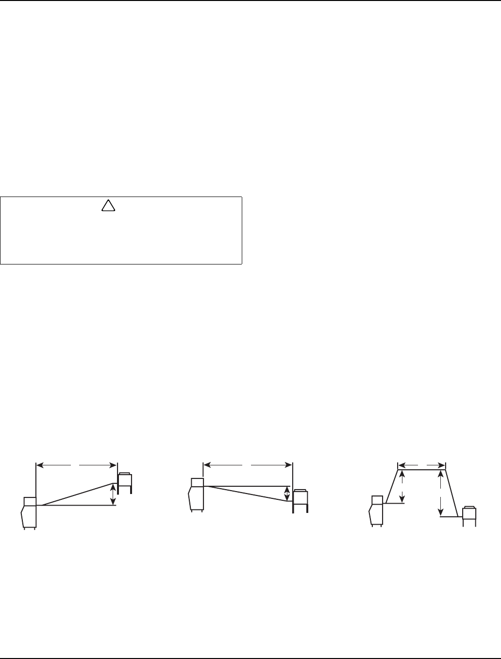
H
R
H
D
H
D
R
Combination of a Rise and a
Horizontal Run
Combination of a Drop and a
Horizontal Run
Combination of a Rise, a Drop
and a Horizontal Run
SV1196 SV1195 SV1194