
Specifications


Table Of Contents
- Q_Model_TOC_uc.pdf
- Model Numbers 1-1
- How to Read a Model Number 1-1
- Ice Cube Sizes 1-1
- Accessories 1-2
- Model/Serial Number Location 1-3
- Warranty 1-4
- Warranty Coverage 1-4
- General 2-1
- Ice Machine Dimensions 2-1
- Ice Storage Bin Dimensions 2-3
- Remote Condenser Dimensions 2-4
- Location of Ice Machine 2-5
- Stacking Two Ice Machines on a Single Storage Bin 2-5
- Ice Machine Heat of Rejection 2-5
- Leveling the Ice Storage Bin 2-6
- Air-Cooled Baffle 2-6
- Electrical Service 2-7
- Self-Contained Electrical Wiring Connections 2-9
- For United Kingdom Only 2-9
- Remote Electrical Wiring Connections 2-10
- Water Supply and Drain Requirements 2-11
- Cooling Tower Applications (Water-Cooled Models) 2-11
- Remote Condenser/Line Set Installation 2-13
- Remote Ice Machine Usage with Non-Manitowoc Multi-Circuit Condensers 2-17
- Installation Check List 2-19
- Additional Checks for Remote Models 2-19
- Before Starting the Ice Machine 2-20
- AuCS® Automatic Cleaning System 2-20
- Component Identification 3-1
- Ice Machine Sequence of Operation Q200/Q280/Q320/Q370/Q420/Q450/Q600/Q800/Q1000/Q1300/Q1600/Q1800 3-2
- Remote Q450/Q600/Q800/Q1000/Q1300/Q1600/Q1800 3-4
- Operational Checks 3-6
- General 4-1
- Ice Machine Inspection 4-1
- Exterior Cleaning 4-1
- Cleaning the Condenser 4-2
- Interior Cleaning and Sanitizing 4-4
- Removal from Service/Winterization 4-12
- Checklist 5-1
- Safety Limit Feature 5-2
- Q_Model_Section_1_uc.pdf
- Q_Model_Section_2_uc.pdf
- Section 2 Installation Instructions
- General
- Ice Machine Dimensions
- Ice Storage Bin Dimensions
- Remote Condenser Dimensions
- Location of Ice Machine
- Stacking Two Ice Machines on a Single Storage Bin
- Ice Machine Heat of Rejection
- Leveling the Ice Storage Bin
- Air-Cooled Baffle
- Electrical Service
- Self-Contained Electrical Wiring Connections
- For United Kingdom Only
- Remote Electrical Wiring Connections
- Water Supply and Drain Requirements
- Cooling Tower Applications (Water-Cooled Models)
- Remote Condenser/Line Set Installation
- Remote Ice Machine Usage with Non-Manitowoc Multi-Circuit Condensers
- Installation Check List
- Additional Checks for Remote Models
- Before Starting the Ice Machine
- AuCS® Automatic Cleaning System
- Section 2 Installation Instructions
- Q_Model_Section_3_uc.pdf
- Q_Model_Section_5_uc.pdf
Installation Instructions Section 2
2-12
Part No. 80-1375-3
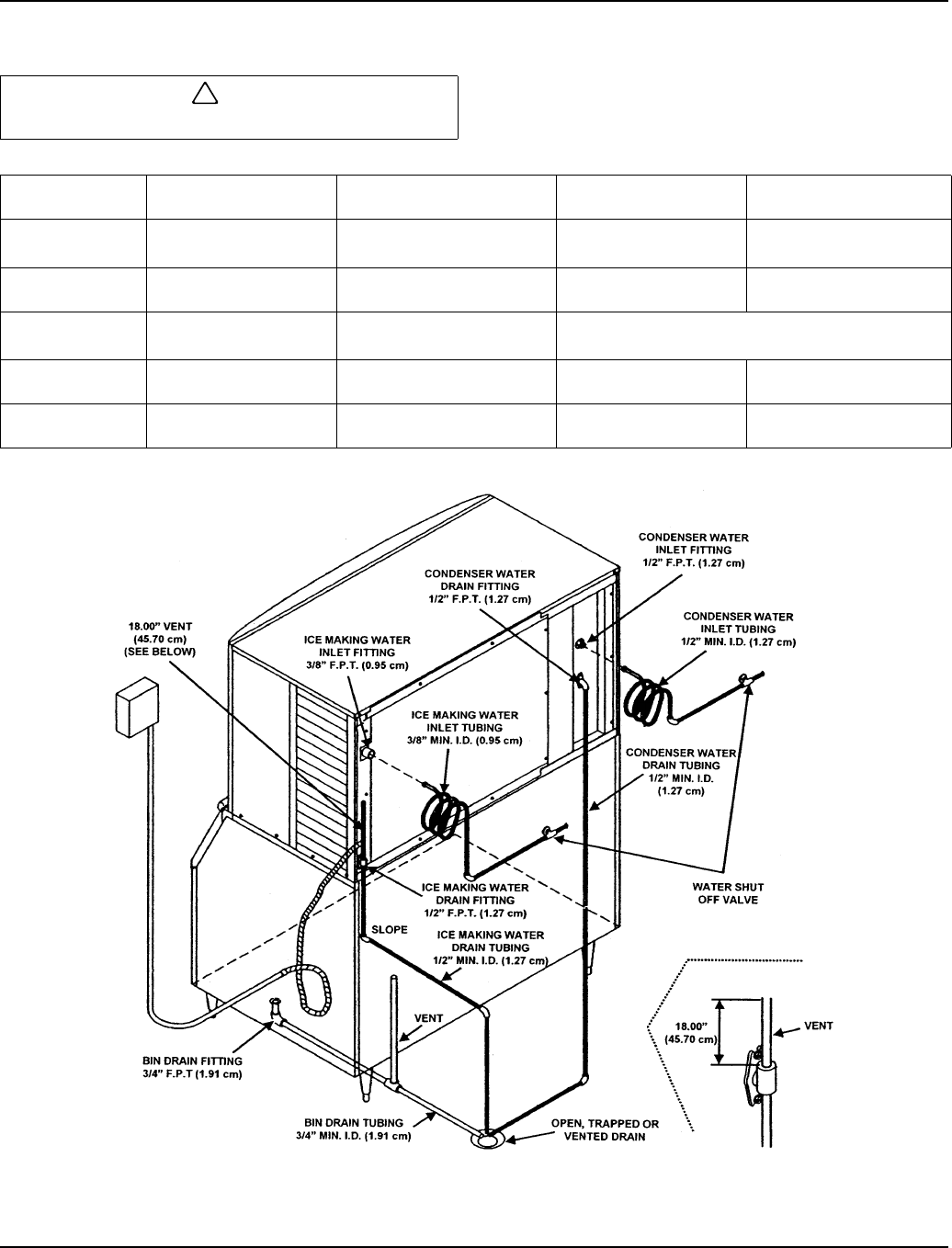
WATER SUPPLY AND DRAIN LINE SIZING/CONNECTIONS
Typical Water Supply Drain Installation
!
Caution
Plumbing must conform to state and local codes.
Location Water Temperature Water Pressure Ice Machine Fitting
Tubing Size Up to Ice
Machine Fitting
Ice Making
Water Inlet
33°F (0.6°C) Min.
90°F (32.2°C) Max.
20 psi (137.9 kPA) Min.
80 psi (551.5 kPA) Max.
3/8" Female
Pipe Thread
3/8" (9.5 mm) minimum
inside diameter
Ice Making
Water Drain
--- ---
1/2" Female
Pipe Thread
1/2" (12.7 mm) minimum
inside diameter
Condenser
Water Inlet
33°F (0.6°C) Min.
90°F (32.2°C) Max.
20 psi (137.9 kPA) Min.
150 psi (1034.2 kPA) Max.
Q1300/Q1600/Q1800 - 1/2" Female Pipe Thread
All Others - 3/8" Female Pipe Thread
Condenser
Water Drain
--- ---
1/2" Female
Pipe Thread
1/2" (12.7 mm) minimum
inside diameter
Bin Drain --- ---
3/4" Female
Pipe Thread
3/4" (19.1 mm) minimum
inside diameter
SV1626