
Specifications


Table Of Contents
- Q_Model_TOC_uc.pdf
- Model Numbers 1-1
- How to Read a Model Number 1-1
- Ice Cube Sizes 1-1
- Accessories 1-2
- Model/Serial Number Location 1-3
- Warranty 1-4
- Warranty Coverage 1-4
- General 2-1
- Ice Machine Dimensions 2-1
- Ice Storage Bin Dimensions 2-3
- Remote Condenser Dimensions 2-4
- Location of Ice Machine 2-5
- Stacking Two Ice Machines on a Single Storage Bin 2-5
- Ice Machine Heat of Rejection 2-5
- Leveling the Ice Storage Bin 2-6
- Air-Cooled Baffle 2-6
- Electrical Service 2-7
- Self-Contained Electrical Wiring Connections 2-9
- For United Kingdom Only 2-9
- Remote Electrical Wiring Connections 2-10
- Water Supply and Drain Requirements 2-11
- Cooling Tower Applications (Water-Cooled Models) 2-11
- Remote Condenser/Line Set Installation 2-13
- Remote Ice Machine Usage with Non-Manitowoc Multi-Circuit Condensers 2-17
- Installation Check List 2-19
- Additional Checks for Remote Models 2-19
- Before Starting the Ice Machine 2-20
- AuCS® Automatic Cleaning System 2-20
- Component Identification 3-1
- Ice Machine Sequence of Operation Q200/Q280/Q320/Q370/Q420/Q450/Q600/Q800/Q1000/Q1300/Q1600/Q1800 3-2
- Remote Q450/Q600/Q800/Q1000/Q1300/Q1600/Q1800 3-4
- Operational Checks 3-6
- General 4-1
- Ice Machine Inspection 4-1
- Exterior Cleaning 4-1
- Cleaning the Condenser 4-2
- Interior Cleaning and Sanitizing 4-4
- Removal from Service/Winterization 4-12
- Checklist 5-1
- Safety Limit Feature 5-2
- Q_Model_Section_1_uc.pdf
- Q_Model_Section_2_uc.pdf
- Section 2 Installation Instructions
- General
- Ice Machine Dimensions
- Ice Storage Bin Dimensions
- Remote Condenser Dimensions
- Location of Ice Machine
- Stacking Two Ice Machines on a Single Storage Bin
- Ice Machine Heat of Rejection
- Leveling the Ice Storage Bin
- Air-Cooled Baffle
- Electrical Service
- Self-Contained Electrical Wiring Connections
- For United Kingdom Only
- Remote Electrical Wiring Connections
- Water Supply and Drain Requirements
- Cooling Tower Applications (Water-Cooled Models)
- Remote Condenser/Line Set Installation
- Remote Ice Machine Usage with Non-Manitowoc Multi-Circuit Condensers
- Installation Check List
- Additional Checks for Remote Models
- Before Starting the Ice Machine
- AuCS® Automatic Cleaning System
- Section 2 Installation Instructions
- Q_Model_Section_3_uc.pdf
- Q_Model_Section_5_uc.pdf
Section 2 Installation Instructions
Part No. 80-1375-3 2-9
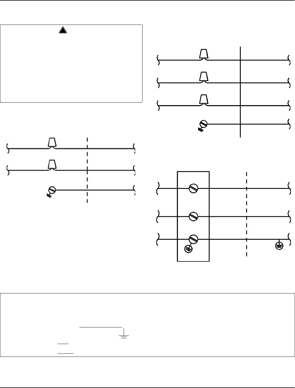
Self-Contained Electrical Wiring Connections
SELF CONTAINED ICE MACHINE
115/1/60 OR 208-230/1/60
SELF CONTAINED ICE MACHINE
208-230/3/60
SELF CONTAINED ICE MACHINE
230/1/50
!
Warning
These diagrams are not intended to show proper
wire routing, wire sizing, disconnects, etc., only the
correct wire connections.
All electrical work, including wire routing and
grounding, must conform to local, state and national
electrical codes.
Though wire nuts are shown in the drawings, the ice
machine field wiring connections may use either
wire nuts or screw terminals.
L
1
L
1
N=115V
OR
L2=208-230V
GROUND
GROUND
ICE MACHINE
CONNECTIONS
SV1258
L
1
L
1
GROUND
GROUND
ICE MACHINE
CONNECTIONS
TO SEPARATE
FUSE/BREAKER
L
2
L
3
L
2
L
3
SV1190
L
1
L
1
N
N
GROUND
GROUND
ICE MACHINE
CONNECTIONS
TO SEPARATE
FUSE/BREAKER.
DISCONNECT ALL
POLES.
SV1191
For United Kingdom Only
As the colours of the wires in the mains lead of the appliance may not correspond with the coloured markings
identifying the terminals in your plug, proceed as follows:
• The wire which is coloured green and yellow must be connected to the terminal in the plug which is marked with
the letter E or by the earth ground symbol
or coloured green or green and yellow.
• The wire coloured blue must be connected to the terminal which is marked with the letter N or coloured black.
• The wire coloured brown must be connected to the terminal which is marked with the letter L or coloured red.
TO SEPARATE
FUSE/BREAKER