Manitowoc Undercounter Ice Machines Technician’s Handbook This manual is updated as new information and models are released. Visit our website for the latest manual. www.manitowocice.
Safety Notices As you work on Manitowoc equipment, be sure to pay close attention to the safety notices in this handbook. Disregarding the notices may lead to serious injury and/or damage to the equipment. Throughout this handbook, you will see the following types of safety notices: ! Warning Text in a Warning box alerts you to a potential personal injury situation. Be sure to read the Warning statement before proceeding, and work carefully.
Procedural Notices As you work on Manitowoc equipment, be sure to read the procedural notices in this handbook. These notices supply helpful information which may assist you as you work. Throughout this handbook, you will see the following types of procedural notices: Important Text in an Important box provides you with information that may help you perform a procedure more efficiently. Disregarding this information will not cause damage or injury, but it may slow you down as you work.
Read These Before Proceeding: ! Caution Proper installation, care and maintenance are essential for maximum performance and troublefree operation of your equipment. Visit our website www.manitowocfsg.com for manual updates, translations, or contact information for service agents in your area. Important Routine adjustments and maintenance procedures outlined in this handbook are not covered by the warranty.
! Warning This equipment contains high voltage electricity and refrigerant charge. Installation and repairs are to be performed by properly trained technicians aware of the dangers of dealing with high voltage electricity and refrigerant under pressure.The technician must also be certified in proper refrigerant handling and servicing procedures. All lockout and tag out procedures must be followed when working on this equipment.
! Warning Do not obstruct machine vents or openings. ! Warning Do not store gasoline or other flammable vapors or liquids in the vicinity of this or any other appliance. ! Warning Do not clean with water jet. ! Warning It is the responsibility of the equipment owner to perform a Personal Protective Equipment Hazard Assessment to ensure adequate protection during maintenance procedures. ! Warning Two or more people are required to move this equipment to prevent tipping.
! Warning When using electric appliances, basic precautions must always be followed, including the following: a. Read all the instructions before using the appliance. b. To reduce the risk of injury, close supervision is necessary when an appliance is used near children. c. Do not contact moving parts. d. Only use attachments recommended or sold by the manufacturer. e. Do not use outdoors. f. For a cord-connected appliance, the following must be included: • Do not unplug by pulling on cord.
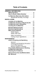
Table of Contents GENERAL INFORMATION Model Numbers . . . . . . . . . . . . . . . . . . . . . 13 How to Read a Model Number . . . . . . . . . 14 Ice Machine Warranty Information . . . . . 15 Residential Warranty Coverage . . . . . 17 INSTALLATION Location of Ice Machine . . . . . . . . . . . . . . 21 Ice Machine Clearance Requirements . . 22 Ice Machine Heat of Rejection . . . . . . . . . 22 Leveling the Ice Machine . . . . . . . . . . . . . 23 Electrical Requirements . . . . . . . . . . . . . .
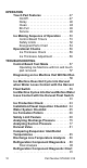
OPERATION Touch Pad Features . . . . . . . . . . . . . . . . On/Off . . . . . . . . . . . . . . . . . . . . . . . . . Delay . . . . . . . . . . . . . . . . . . . . . . . . . Clean . . . . . . . . . . . . . . . . . . . . . . . . . Bin Full . . . . . . . . . . . . . . . . . . . . . . . . Service . . . . . . . . . . . . . . . . . . . . . . . . Ice Making Sequence of Operation . . . . Control Board Timers . . . . . . . . . . . . Safety Limits . . . . . . . . . . . . . . . . . . . . Energized Parts Chart . . . .
COMPONENT CHECK PROCEDURES Main Fuse . . . . . . . . . . . . . . . . . . . . . . . . . 95 Bin Switch . . . . . . . . . . . . . . . . . . . . . . . . . 96 Touch Pad . . . . . . . . . . . . . . . . . . . . . . . . . 98 Float Switch . . . . . . . . . . . . . . . . . . . . . . . 100 Compressor Electrical Diagnostics . . . . 102 Fan Cycle Control . . . . . . . . . . . . . . . . . . . 104 High Pressure Cutout (HPCO) Control . . 105 Filter-Driers . . . . . . . . . . . . . . . . . . . . . . . .
CHARTS Cycle Times, 24 Hr. Ice Production and Refrigerant Pressure Charts . . . . . . . . . . U0140 Self-contained Air-cooled . . . . U0140 Self-contained Water-cooled . . U0190 Self-contained Air-cooled . . . . U0240 Self-contained Air-cooled . . . . U0240 Self-contained Water-cooled . . U0310 Self-contained Air-cooled . . . . U0310 Self-contained Water-cooled . . 121 122 123 124 125 126 127 128 DIAGRAMS Wiring Diagrams . . . . . . . . . . . . . . . . . . . Wiring Diagram - All Models . . . . . . . .
General Information Model Numbers This manual covers the following models: Self-contained Air-cooled Self-contained Water-cooled UD0140A UD0140W UD0140AE UD0140WE UY0140A UY0140W UY0140AE UY0140WE UR0140A -- UR0140AE -- UD0190A -- UD0190AE -- UY0190A -- UY0190AE -- UR0190A -- UR0190AE -- UD0240A UD0240W UD0240AE UD0240WE UY0240A UY0240W UY0240AE UY0240WE UR0240A -- UR0240AE -- UD0310A UD0310W UD0310AE UD0310WE UY0310A UY0310W UY0310AE UY0310WE UR0310A -- UR031
How to Read a Model Number Cube Size Capacity Condenser Type Series U D 0140 A E E - WRAS 50Hz R - Regular D - Dice Y - Half-dice A - Air-cooled W - Water-cooled ! Warning An ice machine contains high voltage electricity and refrigerant charge. Repairs are to be performed by properly trained refrigeration technicians aware of the dangers of dealing with high voltage electricity and refrigerant under pressure.
Ice Machine Warranty Information Owner Warranty Registration Card General Warranty coverage begins the day the ice machine is installed. Important Complete and mail the OWNER WARRANTYREGISTRATION CARD as soon as possible to validate the installation date. If the OWNER WARRANTY REGISTRATION CARD is not returned, Manitowoc will use the date of sale to the Manitowoc Distributor as the first day of warranty coverage for your new ice machine.
Exclusions The following items are not included in the ice machine’s warranty coverage: 1. Normal maintenance, adjustments and cleaning as outlined in this manual. 2. Repairs due to unauthorized modifications to the ice machine or use of non-standard parts without prior written approval from Manitowoc Ice. 3. Damage caused by improper installation of the ice machine, electrical supply, water supply or drainage, or damage caused by floods, storms, or other acts of God. 4.
RESIDENTIAL WARRANTY COVERAGE What Does this Limited Warranty Cover? Subject to the exclusions and limitations below, Manitowoc Ice (“Manitowoc”) warrants to the original consumer that any new ice machine manufactured by Manitowoc (the “Product”) shall be free of defects in material or workmanship for the warranty period outlined below under normal use and maintenance, and upon proper installation and start-up in accordance with the instruction manual supplied with the Product.
What Is Not Covered? This limited warranty does cover, and you are solely responsible for the costs of: (1) periodic or routine maintenance, (2) repair or replacement of the Product or parts due to normal wear and tear, (3) defects or damage to the Product or parts resulting from misuse, abuse, neglect, or accidents, (4) defects or damage to the Product or parts resulting from improper or unauthorized alterations, modifications, or changes; and (5) defects or damage to any Product that has not been installe
How State Law Applies This limited warranty gives you specific legal rights, and you may also have rights that vary from state to state or from one jurisdiction to another. Registration Card To secure prompt and continuing warranty service, this warranty registration card must be completed and sent to Manitowoc within thirty (30) days from the sale date. Complete the following registration card and send it to Manitowoc at the address shown above. Retain a copy for your records.
This Page Intentionally Left Blank 20 Part Number STH042 3/14
Installation Location of Ice Machine The location selected for the ice machine must meet the following criteria. If any of these criteria are not met, select another location. • The location must be indoors. • The location must be free of airborne and other contaminants. • Air temperature: Must be at least 40°F (4°C) but must not exceed 110°F (43.4°C). • The location must not be near heat-generating equipment or in direct sunlight.
Ice Machine Clearance Requirements Self-contained Air-cooled Self-contained Water-cooled Top/Sides 5" (127 mm)* 5" (127 mm)* Back 5" (127 mm)* 5" (127 mm)* *NOTE: The ice machine may be built into a cabinet. There is no minimum clearance requirement for the top or left and right sides of the ice machine. The listed values are recommended for efficient operation and servicing only.
Leveling the Ice Machine 1. Screw the leveling legs onto the bottom of the ice machine. 2. Screw the foot of each leg in as far as possible. ! Caution The legs must be screwed in tightly to prevent them from bending. 3. Move the ice machine into its final position. 4. Level the ice machine to ensure that the siphon system functions correctly. Use a level on top of the ice machine. Turn each foot as necessary to level the ice machine from front to back and side to side.
Electrical Requirements Voltage The maximum allowable voltage variation is ±10% of the rated voltage on the ice machine model/serial number plate at start-up (when the electrical load is highest). Fuse/Circuit Breaker A separate fuse/circuit breaker must be provided for each ice machine. Total Circuit Ampacity The total circuit ampacity is used to help select the wire size of the electrical supply. The wire size (or gauge) is also dependent upon location, materials used, length of run, etc.
Electrical Specifications Air-cooled Ice Machine Ice Machine U140 U190 U240 U310 Voltage Phase Cycle Max. Fuse/ Circuit Breaker Total Amps 115/1/60 15 5.0 208-230/1/60 15 2.5 230/1/50 15 2.5 115/1/60 15 6.0 208-230/1/60 15 2.5 230/1/50 15 2.5 115/1/60 15 7.0 208-230/1/60 15 4.0 230/1/50 15 4.0 115/1/60 15 10.0 208-230/1/60 15 4.5 230/1/50 15 4.
Water-cooled Ice Machine Ice Machine U140 U240 U310 Voltage Phase Cycle Max. Fuse/ Circuit Breaker Total Amps 115/1/60 15 5.0 208-230/1/60 15 2.5 230/1/50 15 2.5 115/1/60 15 7.0 208-230/1/60 15 4.0 230/1/50 15 4.0 115/1/60 15 10.0 208-230/1/60 15 4.5 230/1/50 15 4.5 NOTE: * Indicates preliminary data ! Warning All wiring must conform to local, state and national codes. ! Warning The ice machine must be grounded in accordance with national and local electrical code.
Water Service/Drains WATER SUPPLY Local water conditions may require treatment of the water to inhibit scale formation, filter sediment, and remove chlorine odor and taste. Important If you are installing a Manitowoc water filter system, refer to the Installation Instructions supplied with the filter system for ice making water inlet connections. ! Warning For ice making, connect to a potable water supply only.
DRAIN CONNECTIONS Follow these guidelines when installing drain lines to prevent drain water from flowing back into the ice machine and storage bin: • Drain lines must have a 1.5-inch drop per 5 feet of run (2.5 cm per meter), and must not create traps. • The floor drain must be large enough to accommodate drainage from all drains. • Install a tee to vent the ice machine drain to the atmosphere. • Insulate drain lines to prevent condensation.
Water Temperature 33°F (0.6°C) min. 90°F (32.2°C) max. 33°F (0.6°C) min. 90°F (32.2°C) max. — Location Ice Making Water Inlet Condenser Water Inlet Part Number STH042 3/14 Condenser Water Drain — 20 psi (1.38 bar) min. 150 psi (10.3 bar) max. 20 psi (1.38 bar) min. 80 psi (5.5 bar) max. Water Pressure 3/8" Female Pipe Thread 3/8" Female Pipe Thread 3/8" Female Pipe Thread Ice Machine Fitting 3/8" (9.5 mm) min. inside diameter 3/8" (9.5 mm) min. inside diameter 3/8" (9.5 mm) min.
This Page Intentionally Left Blank 30 Part Number STH042 3/14
Maintenance Interior Cleaning and Sanitizing GENERAL Clean and sanitize the ice machine every six months for efficient operation. If the ice machine requires more frequent cleaning and sanitizing, consult a qualified service company to test the water quality and recommend appropriate water treatment. The ice machine must be taken apart for cleaning and sanitizing. ! Caution Use only Manitowoc approved Ice Machine Cleaner (part number 94-0546-3) and Sanitizer (part number 94-0565-3).
TOUCH PAD OPERATION Pressing and holding the clean button for 3 seconds starts the clean cycle. The Clean & On/Off lights energize indicating the clean cycle has started and ice making will automatically start when the Clean cycle is complete. • Setting the ice machine to stop after the clean cycle: Press the On/Off button. The On/Off light will de-energize indicating the ice machine will stop after the clean cycle. • Pausing the cleaning cycle: Press the Clean button.
! Caution Do not mix Ice Machine Cleaner and Sanitizer solutions together. It is a violation of Federal law to use these solutions in a manner inconsistent with their labeling. Step 3 To start a cleaning cycle, press the Clean button. Water will flow through the water dump valve and down the drain. Wait until the water trough refills, then add the proper amount of ice machine cleaner to the water trough.
Step 5 Mix a solution of cleaner and warm water. Depending on the amount of mineral buildup, a larger quantity of solution may be required. Use the ratio in the table below to mix enough solution to thoroughly clean all parts. Solution Type Water Mixed with Cleaner 1 gal. (4 l) 16 oz (500 ml) cleaner Use half of the cleaner/water solution to clean all components.
Step 7 Mix a solution of sanitizer and warm water. Solution Type Water Mixed With Sanitizer 3 gal. (12 l) 2 oz (60 ml) sanitizer Use half of the sanitizer/water solution to sanitize all removed components. Use a spray bottle to liberally apply the solution to all surfaces of the removed parts or soak the removed parts in the sanitizer/water solution. Do not rinse parts after sanitizing. Step 8 Use half of the sanitizer/water solution to sanitize all foodzone surfaces of the ice machine and bin.
REMOVE PARTS FOR CLEANING ! Warning Disconnect electric power to the ice machine at the electric switch box before proceeding. A. Remove the Harvest Float Switch and Ice Thickness Float Switch • Pull forward on the bottom of the bracket until clear of the tab, then slide bracket upward to remove the bracket and float as an assembly. At this point, the float switch’s can easily be cleaned. If complete removal is desired follow the wires to the bulkhead grommet (exit point) in the back wall.
WIRE CONNECTORS ARE LOCATED BEHIND BULKHEAD PULL THROUGH GROMMET TO DISCONNECT HARVEST FLOAT SWITCH & BRACKET ICE THICKNESS FLOAT SWITCH & BRACKET DISCONNECT WIRES FOR COMPLETE REMOVAL Part Number STH042 3/14 37
• • • B. Remove the Water Trough Remove the upper thumbscrew. While supporting the water trough remove the thumbscrew from beneath the water trough. Remove the water trough from the bin area.
• • C. Remove the Ice Damper Remove thumbscrew from bin switch cover. Support ice damper and then pull bin switch cover and ice damper forward to remove. 1. REMOVE THUMBSCREW 2.
D. Remove the Water Distribution Tube Distribution tube thumbscrews are retained to prevent loss. Loosen thumbscrews but do not pull thumbscrews out of distribution tube. • Loosen the two outer screws and pull forward on the distribution tube to release. NOTE: For ease of assembly when reinstalling the water distribution tube, install the top edge first. • 1. LOOSEN THUMBSCREWS 2.
Preventative Maintenance Cleaning This cleaning procedure can be performed between the bi-annual cleaning and sanitizing cycles. This procedure does not require removing the ice from the bin. Step 1 Press the On/Off button after ice falls from the evaporator at the end of a Harvest cycle. Or, press the On/Off button and allow the ice to melt off the evaporator. ! Caution Never use anything to force ice from the evaporator. Damage may result. .
Ice Machine Inspection Check all water fittings and lines for leaks. Also, make sure the refrigeration tubing is not rubbing or vibrating against other tubing, panels, etc. Do not put anything (boxes, etc.) in front of the ice machine. There must be adequate airflow through and around the ice machine to maximize ice production and ensure long component life. Exterior Cleaning Clean the area around the ice machine as often as necessary to maintain cleanliness and efficient operation.
Cleaning the Condenser General ! Warning Disconnect electric power to the ice machine head section and the remote condensing unit at the electric service switches before cleaning the condenser. A dirty condenser restricts airflow, resulting in excessively high operating temperatures. This reduces ice production and shortens component life. • Clean the condenser at least every six months. ! Warning The condenser fins are sharp. Use care when cleaning them.
Removal from Service/Winterization 1. Clean and sanitize the ice machine. 2. Press the On/Off button to turn off the ice machine. 3. Turn off the water supply, disconnect and drain the incoming ice-making water line at the rear of the ice machine and drain the water trough. 4. Energize the ice machine, wait one minute for the water inlet valve to open and blow compressed air in both the incoming water and the drain openings in the rear of the ice machine to remove all water. 5.
Bin Removal 1. Disconnect power. 1. Remove all ice from bin. 2. Loosen screws and slide clips to release. 3. Disconnect clamp and remove bin drain. 4. Disconnect touch pad communication cable. 5. Slide bin forward to remove. NOTE: When reinstalling the bin, insure the bin seal is in place and is not pinched/folded as it mates to the cabinet. A water tight seal is required to prevent future condensation or water leakage from entering the ice machine base.
This Page Intentionally Left Blank 46 Part Number STH042 3/14
Operation Touch Pad Features The touch pad offers a series of pressure sensitive buttons to control ice machine operation and provide operational status. On/Off - Blue = Machine On Off = Machine Is Off Delay - Blue = Delay Mode On Off = Delay Mode Is Off Clean - Yellow = Clean Cycle On Off = Cleaning is Off Bin Full - Blue = Bin Is Full Off = Bin Is Not Full Service - Red Solid or Flashing = Needs Service Off = Doesn’t Need Service ON/OFF The On/Off Button is used to start and stop ice making.
DELAY Pressing the Delay button will start a delay period. The ice machine will finish the freeze and harvest cycle and then start the delay period. • Pressing the button once will start a 4 hour delay period. • Pressing the button twice will start a 12 hour delay period. • Pressing the button three times will start a 24 hour delay period. • Pressing the button four times will cancel the delay periods. NOTE: The delay period will be canceled if power is interrupted to the ice machine.
BIN FULL The Bin Full light energizes when the bin is full or is de-energized if the bin is not full. SERVICE The service light indicates the machine needs attention. • Refer to safety limits if this light is energized.
Ice Making Sequence of Operation NOTE: The On/Off button must be depressed and the ice damper must be closed before the ice machine will start. Water Purge Cycle The ice machine purges any remaining water from the water trough down the drain. Freeze Cycle Prechill - The refrigeration system chills the evaporator before water flow over the evaporator starts. The water inlet valve energizes during the pre-chill and remains on until the ice thickness float switch is satisfied.
CONTROL BOARD TIMERS • The ice machine is locked into the freeze cycle for 6 minutes before a harvest cycle can be initiated. The freeze time lock in feature is bypassed on the initial cycle (manual start or after a full bin/safety limit condition). If the Harvest float Switch is in the down position for 10 continuous seconds during the start of a freeze cycle, a harvest sequence is initiated. • The maximum freeze time is 60 minutes at which time the control board automatically initiates a harvest sequence.
SAFETY LIMITS Safety limits are stored and indicated by the control board. The number of cycles required to stop the ice machine varies for each safety limit. Safety limits can be reset by pressing the On/Off button and starting a new ice making cycle. A safety limit is indicated by a flashing Service Light on the touch pad. Safety Limit 1 If the freeze time reaches 60 minutes, the control board automatically initiates a harvest cycle.
Safety Limit 3 If the freeze time reaches 4 minutes and water is not sensed (float remains down for 10 continuous seconds) the ice machine stops. • Safety Limit 3 is bypassed on the initial cycle (manual start or after a full bin/safety limit condition). For all subsequent cycles if the freeze time reaches 4 minutes and water is not sensed, the ice machine stops and initiates a 30 minute delay period.
Part Number STH042 3/14 3. Pre chill Freeze Sequence 2. Refrigeration System Start-up Initial Start-up 1.
Part Number STH042 3/14 55 OFF OFF OFF OFF ON ON OFF OFF OFF OFF ON** OFF OFF ON FOR 20 SECONDS THEN OFF OFF OFF ON ON ON CLOSED CLOSED CLOSED OPEN THEN CLOSED CLOSED CLOSED CLOSED CLOSED THEN OPEN Until bin switch re-closes Bin switch activation 20 seconds Until Harvest Float Switch closes for 10 continual seconds * Condenser Fan Motor: The fan motor is wired through a fan cycle pressure control; therefore, it may cycle on and off.
Operational Checks ICE THICKNESS CHECK After a harvest cycle, inspect the ice cubes in the ice storage bin. The ice bridge connects the ice cubes and must be set to maintain an ice bridge thickness of 1/8" (3.2 mm). To adjust the thickness of the bridge refer to ice thickness adjustment. ICE THICKNESS ADJUSTMENT The ice thickness can be adjusted to three levels. 1. Pull forward on the bottom of the bracket until clear of the tab. 2. Slide the bracket over the desired tab and release.
Troubleshooting Control Board Test Mode NOTE: The ice damper/bin switch can be open or closed and does not effect the operation of the test mode. To enter the test mode press and hold the test button on the control board for 3 seconds.
Diagnosing an Ice Machine that Will Not Run ! Warning High (line) voltage is applied to the control board at all times. Removing the control board fuse or pressing the power button will not remove the power supplied to the control board. 1. Verify primary voltage is supplied to ice machine and the fuse/circuit breaker is closed. 2. Verify control board fuse is okay. NOTE: If any control board lights are on, the fuse is okay. 3. Verify the bin switch functions properly.
Ice Machine Does Not Cycle Into Harvest when Water Loses Contact with the Harvest Float Switch NOTE: The ice machine will make a thick or double slab when a new freeze cycle is started with ice already present on the evaporator. Two of the most common scenarios are: • Power is cycled off/on with ice on the evaporator. • The ice damper/bin switch is opened/closed in the harvest cycle before the ice releases. Remove all ice from the evaporator before starting diagnostic procedures.
Step 3 Disconnect the harvest float switch wire from the control board and place a jumper on the control board harvest float switch terminals. Bypass the freeze time lock-in feature by pressing the power button to cycle the ice machine off/on. Wait until water flows over the evaporator, then refer to chart. Result Correction 10 seconds into the freeze cycle the ice machine cycles from freeze to harvest and the control board harvest light energizes.
Ice Machine Cycles Into Harvest Before Water loses Contact with the Harvest Float Switch Step 1 Disconnect power to the ice machine, remove the electrical panel to allow viewing of the control board lights and pull the wire connector for the harvest float switch through the bulkhead and disconnect.
Step 2 Reapply power and press the power button to cycle the ice machine off/on and bypass the freeze time lock-in feature. Wait until water flows over the evaporator, then refer to chart. Result Correction The harvest light does not come on and the ice machine stays in freeze. Refer to Float Switch Diagnostics The harvest light comes on but the ice machine stays in a freeze cycle. The ice machine is in a 6 minute freeze lock - Cycle on/off and retest.
Ice Production Check The amount of ice a machine produces directly relates to the operating water and air temperatures. This means an ice machine with a 70°F (21°C) ambient temperature and 50°F (10°C) water produces more ice than the same ice machine with 90°F (32°C) ambient and 70°F (21°C) water. 1. Determine the ice machine operating conditions: Air temp entering condenser: ____° Air temp around ice machine: ____° Water temp entering sump trough: ____° 2.
Installation/Visual Inspection Checklist Ice machine is not level • Level the ice machine Condenser is dirty • Clean the condenser Water filtration is plugged (if used) • Install a new water filter Water drains are not run separately and/or are not vented • Run and vent drains according to the Installation Manual 64 Part Number STH042 3/14
Water System Checklist A water-related problem often causes the same symptoms as a refrigeration system component malfunction. Example: A water dump valve leaking during the freeze cycle, a system low on charge, and a starving TXV have similar symptoms. Water system problems must be identified and eliminated prior to replacing refrigeration components.
Ice Formation Pattern Evaporator ice formation pattern analysis is helpful in ice machine diagnostics. Analyzing the ice formation pattern alone cannot diagnose an ice machine malfunction. However, when this analysis is used along with Manitowoc’s Refrigeration System Operational Analysis Table, it can help diagnose an ice machine malfunction. OUTLET OUTLET INLET U0140 INLET U0190 U0240 U0310 Examples of Evaporator Tubing Routing Normal Ice Formation Ice forms across the entire evaporator surface.
Extremely Thin at Evaporator Outlet There is no ice, or a considerable lack of ice formation on the outlet of the evaporator. Examples: No ice at all at the outlet of the evaporator, but ice forms at the inlet half of the evaporator. Or, the ice at the outlet of the evaporator reaches the correct thickness, but the outlet of the evaporator already has 1/2" to 1" of ice formation. Possible cause: Water loss, low on refrigerant, starving TXV, hot water supply, faulty float valve, etc.
Safety Limit Feature In addition to the standard safety controls, your Manitowoc ice machine features built-in safety limits that will stop the ice machine if conditions arise which could cause a major component failure. Service Light: The service light energizes whenever a safety limit has been exceeded. Safety Limit 1 If the freeze time reaches 60 minutes, the control board automatically initiates a harvest cycle.
Safety Limit 3 If the freeze time reaches 4 minutes and water is not sensed (float remains down for 10 continuous seconds) the ice machine stops. • Safety Limit 3 is bypassed on the initial cycle (manual start or after a full bin/safety limit condition). For all subsequent cycles if the freeze time reaches 4 minutes and water is not sensed, the ice machine stops and initiates a 30 minute delay period.
Determining Which Safety Limit Stopped the Ice Machine: When a safety limit condition causes the ice machine to stop, the safety limit light on the control board continually flashes on and off. CONTROL BOARD SAFETY LIMIT LIGHT OPERATION, BEFORE THE POWER BUTTON HAS BEEN CYCLED ON/OFF: Watch the safety limit lights on the control board: • SL#1 flashes = 3 or more 60 minute cycles • SL#1 continuously on = 6 consecutive 60 minute freeze cycles • SL#2 flashes = 3 consecutive 3.
Safety Limit Checklist The following checklists are designed to assist the service technician in analysis. However, because there are many possible external problems, do not limit your diagnosis to only the items listed. Safety Limit #1 Freeze time exceeds 60 minutes for 3 consecutive freeze cycles.
Refrigeration System • Non-Manitowoc components • Improper refrigerant charge • Defective compressor • TXV starving or flooding (check bulb mounting) • Non-condensable in refrigeration system • Plugged or restricted high side refrigerant lines or component • Defective harvest valve 72 Part Number STH042 3/14
Safety Limit #2 Harvest time exceeds 3.5 minutes for 100 Consecutive harvest cycles. Possible Cause Checklist Improper installation • Refer to “Installation/Visual Inspection Checklist” on page 64. Water System • Water area (evaporator) dirty • Dirty/defective water dump valve • Vent tube not installed on water outlet drain • Water freezing behind evaporator • Plastic extrusions and gaskets not securely mounted to the evaporator • Low water pressure (20 psig min.
Safety Limit 3 Freeze time reaches 4 minutes and water is not sensed. Possible Cause Checklist Improper installation • Refer to “Installation/Visual Inspection Checklist” on page 64. Water System • Dirty/defective water dump valve • Low water float valve dirty or defective • Vent tube not installed on water outlet drain • Low water pressure (20 psig min.
Analyzing Discharge Pressure 1. Determine the ice machine operating conditions: Air temp. entering condenser ______ Air temp. around ice machine ______ Water temp. entering sump trough ______ 2. Refer to “Cycle Times, 24 Hr. Ice Production and Refrigerant Pressure Charts” on page 121 for ice machine being checked. Use the operating conditions determined in step 1 to find the published normal discharge pressures. Freeze Cycle ______ Harvest Cycle ______ 3. Perform an actual discharge pressure check.
Discharge Pressure High Checklist Improper Installation • Refer to “Installation/Visual Inspection Checklist” on page 64.
Analyzing Suction Pressure The suction pressure gradually drops throughout the freeze cycle. The actual suction pressure (and drop rate) changes as the air and water temperature entering the ice machine changes. These variables also determine the freeze cycle times. To analyze and identify the proper suction pressure drop throughout the freeze cycle, compare the published suction pressure to the published freeze cycle time. NOTE: Analyze discharge pressure before analyzing suction pressure.
Procedure Step 1. Determine the ice machine operating conditions. Example: Air temp. entering condenser: 90°F/32.2°C Air temp. around ice machine: 80°F/26.7°C Water temp. entering water fill valve: 70°F/21.1°C 2A. Refer to “Cycle Time” and “Operating Pressure” charts for ice machine model being checked. Using operating conditions from Step 1, determine published freeze cycle time and published freeze cycle suction pressure. Example: Published freeze cycle time: 14.8 - 15.
Suction Pressure High Checklist Improper Installation • Refer to “Installation/Visual Inspection Checklist” on page 64. Discharge Pressure • Discharge pressure is too high, and is affecting suction pressure, refer to “Discharge Pressure High Checklist” on page 76.
Suction Pressure Low Checklist Improper Installation • Refer to “Installation/Visual Inspection Checklist” on page 64. Discharge Pressure • Discharge pressure is too low, and is affecting suction pressure, refer to “Freeze Cycle Discharge Pressure Low Checklist” Improper Refrigerant Charge • Undercharged • Wrong type of refrigerant Other • Non-Manitowoc components in system • Improper water supply over evaporator refer to “Water System Checklist” on page 65.
Harvest Valve General The harvest valve is an electrically operated valve that opens when energized, and closes when deenergized. Normal Operation The valve is de-energized (closed) during the freeze cycle and energized (open) during the harvest cycle. The valve is positioned between the receiver and the evaporator and performs two functions: 1. Prevents refrigerant from entering the evaporator during the freeze cycle. The harvest valve is not used during the freeze cycle.
Harvest Valve Analysis The valve can fail in two positions: • Valve will not open in the harvest cycle. • Valve remains open during the freeze cycle. VALVE WILL NOT OPEN IN THE HARVEST CYCLE Although the circuit board has initiated a harvest cycle, the evaporator temperature remains unchanged from the freeze cycle.
Use the following procedure and table to help determine if a harvest valve is remaining partially open during the freeze cycle. 1. Wait five minutes into the freeze cycle. 2. Feel the inlet of the harvest valve(s). Important Feeling the harvest valve outlet or across the harvest valve itself will not work for this comparison. The harvest valve outlet is on the suction side (cool refrigerant). It may be cool enough to touch even if the valve is leaking. 3. Feel the compressor discharge line.
Findings Comments The inlet of the harvest valve is cool enough to touch and the compressor discharge line is hot. This is normal as the discharge line should always be too hot to touch and the harvest valve inlet, although too hot to touch during harvest, should be cool enough to touch after 5 minutes into the freeze cycle. Cool & Hot The inlet of the harvest valve is hot and approaches the temperature of a hot compressor discharge line.
Comparing Evaporator Inlet/Outlet Temperatures The temperatures of the suction lines entering and leaving the evaporator alone cannot diagnose an ice machine. However, comparing these temperatures during the freeze cycle, along with using Manitowoc’s Refrigeration System Operational Analysis Table, can help diagnose an ice machine malfunction. The actual temperatures entering and leaving the evaporator vary by model, and change throughout the freeze cycle.
Discharge Line Temperature Analysis GENERAL Knowing if the discharge line temperature is increasing, decreasing or remaining constant can be an important diagnostic tool. Maximum compressor discharge line temperature on a normally operating ice machine steadily increases throughout the freeze cycle. Comparing the temperatures over several cycles will result in a consistent maximum discharge line temperature. Ambient air temperatures affect the maximum discharge line temperature.
Discharge Line Temperature Above 150°F (66°C) at End of Freeze Cycle: Ice machines that are operating normally will have consistent maximum discharge line temperatures above 150°F (66°C). Verify the expansion valve sensing bulb is positioned and secured correctly. Discharge Line Temperature Below 150°F (66°C) at End of Freeze Cycle Ice machines that have a flooding expansion valve will have a maximum discharge line temperature that decreases each cycle.
Refrigeration Component Diagnostics All electrical and water related problems must be corrected before these charts will work properly. These tables must be used with charts, checklists and other references to eliminate refrigeration components not listed and external items and problems that will cause good refrigeration components to appear defective. The tables list four different defects that may affect the ice machine’s operation.
PROCEDURE Step 1 Complete each item individually in the “Operational Analysis” column. Enter check marks (✓) in the boxes. Each time the actual findings of an item in the “Operational Analysis” column matches the published findings on the table, enter a check mark. Example: Freeze cycle suction pressure is determined to be low. Enter a check mark in the “low” box. Perform the procedures and check all information listed. Each item in this column has supporting reference material.
FINAL ANALYSIS The column with the highest number of check marks identifies the refrigeration problem. Column 1 – Harvest Valve Leaking A leaking harvest valve must be replaced. Column 2 – Low Charge/TXV Starving Normally, a starving expansion valve only affects the freeze cycle pressures, not the harvest cycle pressures. A low refrigerant charge normally affects both pressures. Verify the ice machine is not low on charge before replacing an expansion valve. Add refrigerant charge in 2 oz.
4 Part Number STH042 3/14 Ice Formation Pattern Ice formation is extremely thin on outlet of evaporator -orNo ice formation on entire evaporator Ice formation is extremely thin on outlet of evaporator -orNo ice formation on entire evaporator Ice formation is normal -orice formation is extremely thin on the bottom of the evaporator or No ice formation on evaporator Ice formation is normal -orNo ice formation on entire evaporator All installation and water related problems must be corrected before proc
Part Number STH042 3/14 Freeze cycle Suction Pressure _______ _______ _______ 1 minute Middle End Stops on safety limit: 1 2 Stops on safety limit: 1 or 2 3 Stops on safety limit: 1 4 Suction pressure is High Suction pressure is Low Suction pressure is High Suction pressure is High If suction pressure is High or Low refer to freeze cycle high or low suction pressure problem checklist to eliminate problems and/or components not listed on this table before proceeding.
Part Number STH042 3/14 93 The harvest valve inlet is COOL and The compressor discharge line is HOT Discharge line temp 150°F (66°C) or higher at the end of freeze cycle The harvest valve inlet is HOT and The compressor discharge line is HOT Discharge line temp 150°F (66°C) or higher at the end of freeze cycle Harvest Valve Leaking harvest Valve Discharge Line Temp. Record freeze cycle discharge line temp at the end of freeze cycle. Final Analysis Enter total number of boxes checked in each column.
This Page Intentionally Left Blank 94 Part Number STH042 3/14
Component Check Procedures Main Fuse Function The control board fuse stops ice machine operation if electrical components fail causing high amp draw. Specifications • The main fuse is 250 Volt, 10 amp. ! Warning High (line) voltage is applied to the control board at all times. Removing the control board fuse or pressing the power button will not remove the power supplied to the control board. Check Procedure 1. If the curtain light is on with the ice damper closed, the fuse is good.
Bin Switch Function Bin switch operation is controlled by the movement of the ice damper. The bin switch has two main functions: 1. Terminating the harvest cycle and returning the ice machine to the freeze cycle. This occurs when the bin switch is opened and closed again within 7 seconds of opening during the harvest cycle. 2. Automatic ice machine shut-off. If the storage bin is full at the end of a harvest cycle, the sheet of cubes fails to clear the ice damper and holds it down.
Ohm Test 1. Disconnect the bin switch wires to isolate the bin switch from the control board. 2. Connect an ohmmeter to the disconnected bin switch wires. 3. Cycle the bin switch open and closed numerous times by opening and closing the water curtain. NOTE: To prevent misdiagnosis: • Always use the water curtain magnet to cycle the switch (a larger or smaller magnet will affect switch operation).
Touch Pad Function User interface to select ice making, delay start or cleaning cycle and provides feedback on ice machine operation.
Ohm Test Disconnect wire from control board and Ohm touch pad and interconnecting wire to verify correct operation. Pressing and depressing the touch pad must open and close the circuit. A switch that functions correctly will close as the button is pressed and open as the button is released. Do not insert electrical probe into end of connector. This will stretch the connector and cause intermittent connection issues.
Float Switch Function Open and close to indicate to the control board the level of water in the water trough. Specifications Normally closed, float operated magnetic reed switch. The float switch contacts are closed in the down position. When water raises the float to the up position the magnet in the float opens the contacts. Check Procedure The ice machine uses two float switches. Ice Thickness Float -Indicates the water level has been reached.
FLOAT CLOSED FLOAT OPEN NOTE: Make adjustments with the ice machine in the off position. Making adjustments during the freeze cycle may produce an initial sheet of ice that is thicker than future cycles.
Compressor Electrical Diagnostics The compressor does not start or will trip repeatedly on overload. Check Resistance (Ohm) Values NOTE: Compressor windings can have very low ohm values. Use a properly calibrated meter. Perform the resistance test after the compressor cools. The compressor dome should be cool enough to touch (below 120°F/49°C) to ensure that the overload is closed and the resistance readings will be accurate. Single Phase Compressors 1.
Compressor Drawing Locked Rotor The two likely causes of this are: • Defective starting component • Mechanically seized compressor To determine which you have: 1. Install high and low side gauge. 2. Try to start the compressor. 3. Watch the pressures closely. • If the pressures do not move, the compressor is seized. Replace the compressor. • If the pressures move, the compressor is turning slowly and is not seized. Check the capacitors and relay.
Fan Cycle Control Function Cycles the fan motor on and off to maintain proper operating discharge pressure. The fan cycle control closes on an increase, and opens on a decrease in discharge pressure. Specifications Cut-In (Close) Cut-Out (Open) U140 U190 250 psig ±5 200 psig ±5 U240 U310 275 psig ±5 225 psig ±5 Model Check Procedure Disconnect electrical power to the ice machine at the electrical service disconnect. Verify fan motor windings are not open or grounded, and fan spins freely.
High Pressure Cutout (HPCO) Control Function Stops the ice machine if subjected to excessive highside pressure. The HPCO control is normally closed, and opens on a rise in discharge pressure. Specifications Cut-out: 450 psig ±10 Cut-in: Automatic reset (Must be below 300 psig to reset). Check Procedure 1. switch to OFF. 2. Connect manifold gauge. 3. Hook voltmeter in parallel across the HPCO, leaving wires attached. 4. On water-cooled models, close the water service valve to the water condenser inlet.
Filter-Driers Liquid Line Filter Drier The filter-drier used on Manitowoc ice machines are manufactured to Manitowoc specifications. The difference between a Manitowoc drier and an offthe-shelf drier is in filtration. A Manitowoc drier has dirt-retaining filtration, with fiberglass filters on both the inlet and outlet ends. This is very important because ice machines have a back-flushing action that takes place during every harvest cycle.
This Page Intentionally Left Blank Part Number STH042 3/14 107
Refrigerant Recovery/Evacuation DEFINITIONS Recover To remove refrigerant, in any condition, from a system and store it in an external container, without necessarily testing or processing it in any way. Recycle To clean refrigerant for re-use by oil separation and single or multiple passes through devices, such as replaceable core filter-driers, which reduce moisture, acidity and particulate matter. This term usually applies to procedures implemented at the field job site or at a local service shop.
REFRIGERANT RE-USE POLICY Manitowoc recognizes and supports the need for proper handling, re-use, and disposal of refrigerants. Manitowoc service procedures require recapturing refrigerants, not venting them to the atmosphere. It is not necessary, in or out of warranty, to reduce or compromise the quality and reliability of your customers’ products to achieve this. Important Manitowoc Ice assumes no responsibility for use of contaminated refrigerant.
4. Recovered refrigerant must come from a “contaminant-free” system. To decide whether the system is contaminant free, consider: • Type(s) of previous failure(s) • Whether the system was cleaned, evacuated and recharged properly following failure(s) • Whether the system has been contaminated by this failure • Compressor motor burnouts and improper past service prevent refrigerant re-use. • Refer to “System Contamination Cleanup” on page 114 to test for contamination. 5.
RECOVERY AND RECHARGING PROCEDURES Do not purge refrigerant to the atmosphere. Capture refrigerant using recovery equipment. Follow the manufacturer’s recommendations. Important Manitowoc Ice assumes no responsibility for the use of contaminated refrigerant. Damage resulting from the use of contaminated refrigerant is the sole responsibility of the servicing company. Important Replace the liquid line drier before evacuating and recharging. Use only a Manitowoc (O.E.M.
SELF-CONTAINED RECOVERY/EVACUATION 1. Place the power button in the OFF position. 2. Install manifold gauge set, charging cylinder/ scale, and recovery unit or two-stage vacuum pump. 3. Open (backseat) the high and low side ice machine service valves, and open high and low side on manifold gauge set. 4. Perform recovery or evacuation: A. Recovery: Operate the recovery unit as directed by the manufacturer’s instructions. B. Evacuation prior to recharging: Pull the system down to 500 microns.
7. Close the high side on the manifold gauge set. Add any remaining vapor charge through the suction service valve (if necessary). NOTE: Manifold gauge set must be removed properly to ensure that no refrigerant contamination or loss occurs. 8. Make sure that all of the vapor in the charging hoses is drawn into the ice machine before disconnecting the charging hoses. A. Run the ice machine in freeze cycle. B. Close the high side service valve at the ice machine. C.
System Contamination Cleanup This section describes the basic requirements for restoring contaminated systems to reliable service. Important Manitowoc Ice assumes no responsibility for the use of contaminated refrigerant. Damage resulting from the use of contaminated refrigerant is the sole responsibility of the servicing company. DETERMINING SEVERITY OF CONTAMINATION System contamination is generally caused by either moisture or residue from compressor burnout entering the refrigeration system.
Contamination/Cleanup Chart Symptoms/Findings Required Cleanup Procedure No symptoms or suspicion of contamination Normal evacuation/ recharging procedure Moisture/Air Contamination symptoms Refrigeration system open to atmosphere for longer than 15 minutes Refrigeration test kit and/or acid oil test shows contamination No burnout deposits in open compressor lines Mild contamination cleanup procedure Mild Compressor Burnout symptoms Oil appears clean but smells acrid Refrigeration test kit or acid oil
MILD SYSTEM CONTAMINATION CLEANUP PROCEDURE 1. Replace any failed components. 2. If the compressor is good, change the oil. 3. Replace the liquid line drier. NOTE: If the contamination is from moisture, use heat lamps during evacuation. Position them at the compressor, condenser and evaporator prior to evacuation. Do not position heat lamps too close to plastic components, or they may melt or warp. 4. Follow the normal evacuation procedure, except replace the evacuation step with the following: A.
SEVERE SYSTEM CONTAMINATION CLEANUP PROCEDURE 1. Remove the refrigerant charge. 2. Remove the compressor. 3. Disassemble the harvest solenoid valve. If burnout deposits are found inside the valve, install a rebuild kit, and replace the TXV and head pressure control valve. 4. Wipe away any burnout deposits from suction and discharge lines at compressor. 5. Sweep through the open system with dry nitrogen. 6. Install a new compressor and new start components. 7.
REPLACING PRESSURE CONTROLS WITHOUT REMOVING REFRIGERANT CHARGE This procedure reduces repair time and cost. Use it when any of the following components require replacement, and the refrigeration system is operational and leak-free. • Fan cycle control • High pressure cut-out control • High side access valve • Low side access valve Important This is a required in-warranty repair procedure. 1. Disconnect power to the ice machine. 2. Follow all manufacturers’ instructions supplied with the pinch-off tool.
FIG. A - “PINCHING OFF” TUBING FIG.
Total System Refrigerant Charge Important This information is for reference only. Refer to the ice machine serial number tag to verify the system charge. Serial plate information overrides information listed on this page.
Charts Cycle Times, 24 Hr. Ice Production and Refrigerant Pressure Charts These charts are used as guidelines to verify correct ice machine operation. Accurate collection of data is essential to obtain the correct diagnosis. • Production and cycle times are for dice cube - Half dice cube cycle times can be 1-2 minutes faster depending on model and ambient temperature. • Ice production checks that are within 10% of the chart are considered normal. This is due to variances in water and air temperature.
U0140 SELF-CONTAINED AIR-COOLED NOTE: These characteristics may vary depending on operating conditions. Cycle Times Freeze Time + Harvest Time = Total Cycle Time Freeze Time Air Temp. Entering Condenser °F/°C 50/10 70/21 90/32 70/21 10.2-11.7 12.4-14.1 13.0-14.8 80/27 11.2-12.8 13.0-14.8 14.6-16.5 90/32 11.8-13.4 14.6-16.5 17.6-19.9 100/38 14.6-16.5 17.6-19.9 19.9-17.6 110/43 16.5-18.7 19.9-17.6 20.3-23.0 Water Temperature °F/°C Harvest Time 1.0-2.
U0140 SELF-CONTAINED WATER-COOLED NOTE: These characteristics may vary depending on operating conditions. Cycle Times Freeze Time + Harvest Time = Total Cycle Time Freeze Time Air Temp. Around Ice Machine °F/°C 50/10 70/21 90/32 70/21 9.8-11.2 11.2-12.8 13.0-14.8 80/27 10.2-11.7 11.8-13.4 13.8-15.6 90/32 11.8-13.4 13.0-14.8 15.5-17.5 100/38 13.0-14.8 15.5-17.5 17.6-19.9 110/43 14.6-16.5 17.6-19.9 20.3-23.0 Water Temperature °F/°C Harvest Time 1.0-2.
U0190 SELF-CONTAINED AIR-COOLED NOTE: These characteristics may vary depending on operating conditions. Cycle Times Freeze Time + Harvest Time = Total Cycle Time Freeze Time Air Temp. Entering Condenser °F/°C 50/10 70/21 90/32 70/21 16.1-18.3 19.8-22.5 21.2-24.0 80/27 19.8-22.5 21.9-24.9 24.5-27.8 90/32 21.9-24.9 23.6-26.8 29.0-32.9 100/38 25.5-29.0 29.1-32.9 32.0-36.2 110/43 29.1-32.9 32.0-36.2 33.6-38.1 Water Temperature °F/°C Harvest Time 1.0-2.
U0240 SELF-CONTAINED AIR-COOLED NOTE: These characteristics may vary depending on operating conditions. Cycle Times Freeze Time + Harvest Time = Total Cycle Time Freeze Time Air Temp. Entering Condenser °F/°C 50/10 70/21 90/32 70/21 14.1-16.1 17.0-19.3 18.6-21.1 80/27 15.2-17.4 18.0-20.5 20.5-23.3 90/32 16.5-18.8 20.5-23.3 22.7-25.8 100/38 19.2-21.8 21.9-24.9 23.6-26.8 110/43 21.9-24.9 23.6-26.8 24.5-27.8 Water Temperature °F/°C Harvest Time 1.0-2.
U0240 SELF-CONTAINED WATER-COOLED NOTE: These characteristics may vary depending on operating conditions. Cycle Times Freeze Time + Harvest Time = Cycle Time Freeze Time Air Temp. Around Ice Machine °F/°C Water Temperature °F/°C 50/10 70/21 90/32 70/21 16.1-18.3 17.0-19.3 18.0-20.5 80/27 16.5-18.8 17.5-19.9 18.6-21.1 90/32 17.0-19.3 18.0-20.5 19.2-21.8 100/38 17.5-19.9 18.6-21.1 19.9-22.5 110/43 18.0-20.5 19.2-21.8 20.5-23.3 Harvest Time 1.0-2.
U0310 SELF-CONTAINED AIR-COOLED NOTE: These characteristics may vary depending on operating conditions. Data on this page is preliminary and subject to change. Cycle Times Freeze Time + Harvest Time = Total Cycle Time Freeze Time Air Temp. Entering Condenser °F/°C 50/10 70/21 90/32 70/21 9.8-11.3 11.8-13.4 14.1-16.1 80/27 10.4-11.9 12.3-14.0 13.5-15.4 90/32 11.0-12.6 13.5-15.4 15.2-17.4 100/38 12.3-14.0 15.2-17.4 17.5-19.9 110/43 15.6-17.8 19.2-21.8 21.2-24.
U0310 SELF-CONTAINED WATER-COOLED NOTE: These characteristics may vary depending on operating conditions. Data on this page is preliminary and subject to change. Cycle Times Freeze Time + Harvest Time = Cycle Time Freeze Time Air Temp. Around Ice Machine °F/°C Water Temperature °F/°C 50/10 70/21 90/32 70/21 9.8-11.3 11.3-12.9 12.0-13.7 80/27 10.0-11.5 11.5-13.2 12.3-14.0 90/32 10.2-11.7 12.3-14.0 12.6-14.3 100/38 10.4-11.9 12.6-14.3 12.8-14.7 110/43 10.6-12.2 12.8-14.7 13.1-15.
Diagrams Wiring Diagrams The following pages contain electrical wiring diagrams Be sure you are referring to the correct diagram for the ice machine you are servicing. ! Warning Always disconnect power before working on electrical circuitry.
WIRING DIAGRAM - ALL MODELS 130 Part Number STH042 3/14
ELECTRONIC CONTROL BOARD WATER PUMP HIGH FLOAT MAIN COMP LOW FLOAT BIN SWITCH WATER LEVEL FLOAT HARVEST SAFETY 1 SAFETY 2 CURTAIN TEST MODE ICE LEVEL FLOAT TEST SWITCH WATER DUMP HARVEST WATER FILL FUSE Part Number STH042 3/14 131
Tubing Schematic - U0140 EVAPORATOR EXPANSION VALVE HEAT EXCHANGER HARVEST SOLENOID STRAINER COMPRESSOR DRIER AIR OR WATER CONDENSER 132 RECEIVER ( WATER COOLED ONLY) Part Number STH042 3/14
Tubing Schematic - U0190/U0240/U0310 EVAPORATOR HEAT EXCHANGER EXPANSION VALVE HARVEST SOLENOID VALVE STRAINER COMPRESSOR AIR OR WATER CONDENSER DRIER RECEIVER (WATER COOLED ONLY) Part Number STH042 3/14 133
This Page Intentionally Left Blank 134 Part Number STH042 3/14
Manitowoc Ice 2110 South 26th Street, P.O. Box 1720 Manitowoc, WI 54221-1720, USA Ph: 920-682-0161 Fax: 920-683-7589 Visit us online at: www.manitowocfoodservice.