
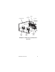
Specifications
78 Part Number STH12 9/10
Sequence of Operation (with ERC)
ELECTRONIC CONTROL
Prerequisites
• Potable water must be connected to the
carbonator pump circuit.
• The ice bank water bath water must cover the
evaporator. The compressor will not start unless
the ice bank control probes are immersed in water.
•CO
2
must be supplied.
Initial Power-up
The control has a 30-second delay when power is
connected, or disconnected and reconnected. The
display will show Pd30 - power delay and 30 seconds
left in the countdown cycle.
Normal Two Circuit Operation
Pressing the COMP/AGIT button will start the water
bath agitator immediately and initiate the 180 second
compressor delay. The display will show Cd99
(compressor delay & 99 seconds) and will start to
count down from 99 seconds after the first 81 seconds
have elapsed. After 180 seconds the compressor and
condenser fan motor energize and the COMP/AGIT
LED flashes. Pressing the CARB A and CARB B
buttons will power the carbonator tank liquid level
control. The corresponding LED flashes to indicate the
pump is running. Pressing the CIRC A & CIRC B
buttons will immediately energize the circulating
pumps and energize the LED constantly. The display
will show the circulating temperature and show the A
circuit. When two circuits are used the readout will
alternate between A and B circuits every 5 seconds.
The compressor and condenser fan will continue to
run until ice contacts the ice bank control probe closest
to the evaporator. When ice contacts the probe, the
COMP/AGIT LED lights constantly and the
compressor and condenser fan motor de-energize.
As the ice bank melts, the ice bank control probe will
lose contact with the ice; the LED will flash and the
compressor and condenser fan motor will restart. This
cycle will repeat as required depending on load.