
Specifications
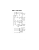


180 Part Number STH12 9/10
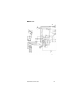
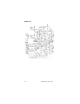
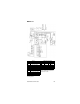
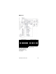
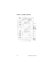
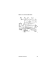
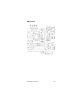
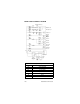
MODEL 44M04 SCHEMATIC DIAGRAM
Component Legend
MS Relay Motor Start
SW Switch ON/OFF
PS Pressure Switch
CR Control Relay
LLC Liquid Level Control
IBC Ice Bank Control
M Motor
TS Terminal Switch
208-230 1 Phase
L1 L2
Export Units Only
SW5
SW6
SW1
SW3
PS2
IBC1
IBC2
R
MS
M1
M2
G
A
M3
M4
CR1
R
S
SW4
CR1-1
CR1-2
LLCA
LLCB
Start
Relay
Fan Motor
MS MS
Start
Cap
Run
Cap
Compressor
Circ. Motor
Carb. “B”
Carb. “A”
Agitator
Motor
Water Booster
SW2
Export Units Only
M6
M7
R
OL
PS1
Air Compressor
Compressor
Lamp #1
Lamp #2
Lamp #3
Lamp #4
Low Water
Pressure
M5