
Specifications
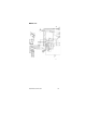
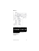


Part Number STH12 9/10 175
MODEL 37K
CO
2
Panel
Agit.
Motor
Carb. Tank
“A”
Carb. Tank
“B”
Remote
Fan
With
Remote
Condenser
Only
High
Pressure
Cut-out
With Air
Cooled
Only
LLC
“A”
IBC
1
IBC
2
LLC
“B”
Carb.
Motor
“A”
Circ.
Motor
“A”
Carb.
Motor
“B”
Circ.
Motor
“B”
Neutral
Ground
Lamp #2
Lamp #1
M6
Refrig.
Comp
Lamp #4
Rfi ti
Tower #1
Lamp #3
24 VAC
Tower #2
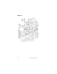
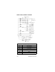
Notes:
On domestic remote and air units, wire #13 goes to terminal #T3 on MS (Motor Start Relay).
On Export remote and air unit wire #13 goes to Neutral (TS#11).
2. All switches shown in their normal position.
Note: Out of CO
2
(24 Y) lamps
#3 and #4 located on dispensing
towers wiring supplied with
conduit and towers. For
Schematic wiring see tower
wiring diagram.
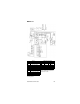
Component Legend
MS Relay Motor Start
SW Switch
PS Pressure Switch
CR Control Relay
LLC Liquid Level Control
IBC Ice Bank Control
M Motor
TS Terminal Strip
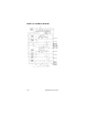
Incoming Power – 3 Phase, 4 wire
wiring supplied by installer from
junction box to fan.
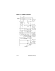
Conductor Color Codes
Domestic Export
L1 Black L1 Black
L2 Red L2 Brown
L3 Brown L3 Brown
L4 White L4 Lt Blue
L5 Grn/Yel L5 Grn/Yel