
Specifications


174 Part Number STH12 9/10
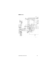
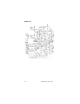
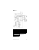
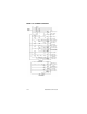
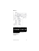
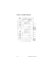
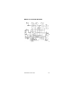
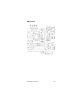
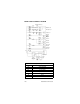
MODEL 37T SCHEMATIC DIAGRAM
Refrig. Compressor
AJR or Remote
Fan Motor
Carb. “A” Motor
Circ. “A” Motor
Carb. “B” Motor
Circ. “B” Motor
Low Incoming Water
Press Carb. “A”
Low Incoming Water
Press Carb. “B”
Booster Pump Motor
Low Incoming Water
Press Booster Pump
Air Comp Motor
Agitator Motor
Refrig Comp Motor
Start Relay
Primary Ice Bank
Control Failure
Filter In By Pass
Carb “A” Low Press
Relay
Carb “B” Low Press
Relay
Booster Pump Low
Press Relay
Out of CO
2
Tower 1
Out of CO
2
Tower 2
Lamp 5
Lamp
6
Lamp 7
Lamp 4
Lamp 3
Lamp 2
Lamp 1
Grn/Yel
Wht
Blk
Red
Brn
Incoming
Power
3 Phase
4 Wire
LLC “A”
LLC “B”
PS-4
PS-5
PS-6
PS-1
PS-2
PS-3
PS-7
SW-9
JI-2
JI-1
99
J2
T1
IBC-2 IBC-1
SW 8
SW 7
SW 6
SW 5
SW 4
SW 3
SW 2
SW 1
CR1
CR1
CR2
CR2
CR3
MS
MS
MS
M9
M8
M1
M2
R
M3
M4
M5
M6
M7
R
R
M5
R
A
CR1
CR2
CR3
A
A