
Specifications
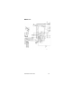
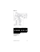

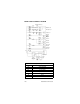

Part Number STH12 9/10 173
MODEL 37T
CO
2
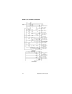
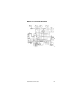
Panel
Lamp #6
Lamp #7
Note:
Lamps 6 and 7 are out of CO
2
lights
located on the dispensing towers.
Wiring is provided with conduit and
towers.
Note:
On domestic remote and air units,
Wire #T3 goes to wire #T3 on
motor start relay.
Water
Bath
Agit.
Motor
M7
Carb. Tank
“A”
Carb. Tank
“B”
Remote
Fan
With
Remote
Condenser
Only
High
Pressure
Cut-out
With Air
Cooled
Only
Fan
M8
PS-6
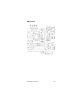
Junction Box
Grn
Blk
Wht
Wht
Blk
Grn
LLC
“B”
IBC
1
M5
IBC
2
LLC
“A”
Carb.
Motor
“A”
Circ.
Motor
“A”
Carb.
Motor
“B”
Circ.
Motor
“B”
Neutral
Ground
Lamp #4
Lamp #5
Lamp
#3
Lamp #2
Lamp #1
Control Box
Field
Connections
Refrigeration
Compressor
Air
Compressor
Motor
Booster
Pump
Motor
Syrup
Stand
SW Filter
By-pass
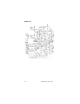
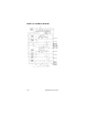
Note: all switches shown in their
normal positions.
Note:
MS Relay Motor Start
SW Switch
PS Pressure Switch
CR Control Relay
LLC Liquid Level Control
IBC Ice Bank Control
M Motor
TTransformer
J Connection Receptacle
P Connector Plug
TS Terminal Strip
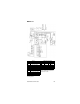
Incoming Power – 3 Phase, 4 wire
wiring supplied by installer from
junction box to fan.
Conductor Color Codes
Domestic Export
L1 Black L1 Black
L2 Red L2 Brown
L3 Brown L3 Brown
L4 White L4 Lt Blue
L5 Grn/Yel L5 Grn/Yel