
Specifications
Part Number STH12 9/10 143
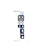
J-17 CALIBRATION BUTTON AND LIGHT
If microprocessor does not go into calibration, remove
connector at J-17. With jumper wire, jump 1st and 2nd
pins on left 3 times in less than 3 seconds. Replace
connector. Calibration light should be on
(microprocessor will be in the calibration mode). White
& white = calibration button. Red & black = calibration
light. If CAL light does not come on, LED is burned out
— replace keyboard.
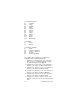
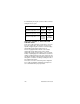
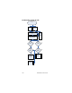
SECONDARY BOARD PIN IDENTIFICATION
J-1 = Valve 2 Flavor 1
J-2 = Valve 2 Flavor 2
J-3 = Valve 4 Flavor 1
J-4 = Valve 4 Flavor 2
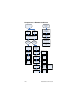
Use a jumper wire to make these connections to
determine if timer is functioning properly.
1. Jump pin 2 or 3 on J-19 and pin 7 or 9 on J-16.
Then jump pin 1 on J-16 to pin 7 or 9 on J-16.
Appropriate valve should energize as long as pins
are jumped.
2. Jump pin 2 or 3 on J-19 and pin 7 or 9 on J-16.
Then jump pin 12 on J-16 to pin 7 or 9 on J-16.
Appropriate valve should pour Extra Large.
3. Jump pin 2 or 3 on J-19 and pin 7 or 9 on J-16.
Then jump pin 2 on J-16 to pin 7 or 9 on J-16.
Appropriate valve should pour Large.
4. Jump pin 2 or 3 on J-19 to pin 7 or 9 on J-16.
Then jump pin 3 on J-16 to pin 7 or 9 on J-16.
Appropriate valve should pour Medium.
5. Jump pin 2 or 3 on J-19 to pin 7 or 9 on J-16.
Then jump pin 4 on J-16 to pin 7 or 9 on J-16.
Appropriate valve should pour Small.
6. Jump pin 2 or 3 on J-19 to pin 5 on J-19. Then
jump pin 5 on J-19 to pin 7 or 9 on J-16.
Appropriate valve should pour Kid Size.