
Specifications
Part Number STH12 9/10 141
Test Procedures: MPC84C Timer/
Selection Board
MPC 84B timers can be placed in the test mode as
follows:
1. Flip power switch OFF.
2. While depressing CAL button on selection pad,
flip power switch ON.
3. Release CAL button when red LED comes on.
Faucets will energize for 4 seconds, each in
sequence, starting with faucet #1 (far left). Timer is
now in the Test Mode. To stop faucets, use one of two
procedures.
• Turn power switch off. This will save the
programmed times. Use this procedure for testing
or sanitizing.
• Push CAL. All programmed times will be saved.
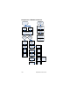
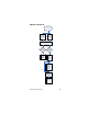
PIN IDENTIFICATION
J-1 = Valve 1 J-6 = Valve 6
J-2 = Valve 2 J-7 = Valve 7
J-3 = Valve 3 J-8 = Valve 8
J-4 = Valve 4 J-9 = Soda
J-5 = Valve 5 J-10 = Water
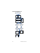
Check for 24 Volts at each solenoid cable connector,
J-1 through J-8, with cables removed.
With cables on, check for 24VAC across solenoids at
dispensing valve while dispensing respective valve.
J-15 Power to valves 1, 2, 3, 4 and microprocessor
J-20 Power to valves 5, 6, 7, 8 and microprocessor
Loss of power at J-15 results in loss of power to valves
1, 2, 3, and 4.
Loss of power at J-20 results in loss of power to valves
5, 6, 7, and 8.