
Specifications


Multiplex Company, Inc.
Component Parts Workbook
45
00218011 Revision B (KAK) 31 July, 2000
Test Procedures
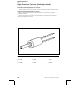
Model MPC64A timer/selection
pad
MPC 64A Timers can be placed in the test
mode as follows:
1. Flip power switch off.
2. While depressing CAL button on selection pad,
flip power switch back on.
3. Release CAL button when red LED comes on.
Faucets will energize for 2 seconds, each in
sequence, starting with faucet #1 (far left).
Timer is now in the Test Mode. To stop faucets,
use one of two procedures:
a. Turn power switch off. This will save the
programmed times. Use this procedure
for testing or sanitizing.
b. Push CAL button. All programmed times
for all stations will go to factory default
times. Default times are:
Size #1: 1 - 1.5 seconds
Size #2: 4 - 4.5 seconds
Size #3: 6 - 6.5 seconds
Size #4: 8 - 8.5 seconds
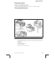
Pin identification
J-7 = Valve 1 J-10 = Valve 4
J-8 = Valve 2 J-11 = Valve 5
J-9 = Valve 3 J-12 = Valve 6
Check for 24 Volts at each solenoid cable
connector, J-7 through J-12, with cables
removed.
With cables on, check for 24 VAC across
solenoids at dispensing valve while dispensing
respective valve.
J-15 Power to Valves 1, 2, 3.
J-20 Power to Valves 4, 5, 6 and
microprocessor.
Loss of power at J-15 results on loss of power
to valves 1, 2, 3.
Loss of power at J-20 results on loss of power
to microprocessor; no valves will work.
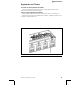
J-16 Station and Sizes:
#1 Stop/Fill
#2 Large
#3 Medium
#4 Small
#5 Valve 6 (or nothing, on a 5 valve
tower)
#6 Valve 5
#7 Valve 4
#8 Valve 3
#9 Valve 2
#10 Valve 1
#11 Blank
#12 Extra Large
Use a jumper wire to make these connections
to determine if timer is functioning properly.
1. Jump pin 1 to pin 5, 6, 7, 8, 9, 10. Appropri-
ate valve should energize as long as pins are
jumped.
2. Jump pin 12 to pin 5, 6, 7, 8, 9, 10. Valves
should pour EXTRA LARGE.
3. Jump pin 2 to pin 5, 6, 7, 8, 9, 10. Valves
should pour LARGE.
4. Jump pin 3 to pin 5, 6, 7, 8, 9, 10. Valves
should pour MEDIUM.
5. Jump pin 4 to pin 5, 6, 7, 8, 9, 10. Valves
should pour SMALL.
J-17 calibration button and light
If microprocessor does not go into calibration,
remove connector at J-17. With jumper wire,
jump 1st and 2nd pins on left 3 times in less than
3 seconds. Replace connector. Calibration light
should be on (microprocessor will be in the
calibration mode). White & white = calibration
button. Red & black = calibration light. If CAL
light does not come on, LED is burned out -
replace keyboard.