MII SERIES MII-250/302 Beverage/Ice Dispenser with Flex Manifold INSTALLATION & SERVICE GUIDE PARTNUMBER 5031216 Manitowoc Beverage Equipment 2100 Future Drive Sellersburg, IN 47172-1868 Tel: 812.246.7000, 800.367.4233 Fax: 812.246.9922 www.manitowocbeverage.com In accordance with our policy of continuous product development and improvement, this information is subject to change at any time without notice.
FOREWORD Manitowoc Beverage Equipment (MBE) developed this manual as a reference guide for the owner/ operator, service agent, and installer of this equipment. Please read this manual before installation or operation of the machine. A qualified service technician should perform installation and startup of this equipment, consult the Troubleshooting Guide within this manual for service assistance. If you cannot correct the service problem, call your MBE Service Agent or Distributor.
TABLE OF CONTENTS FOREWORD ........................................................................................................ 3 UNPACKING AND INSPECTION ......................................................................... 3 WARRANTY INFORMATION ............................................................................... 3 SAFETY ............................................................................................................... 6 IMPORTANT SAFETY INSTRUCTIONS .......................
Installation and Service Manual TABLE OF CONTENTS CARBONATION ............................................................................................................. 24 SYRUP DELIVERY SYSTEM .......................................................................................... 24 RACKING ....................................................................................................................... 24 B-I-B ...................................................................................
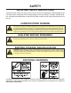
SAFETY IMPORTANT SAFETY INSTRUCTIONS Carefully read all safety messages in this manual. Learn how to operate the MII unit properly. Do not allow anyone to operate the unit without proper training and keep it in proper working condition. Unauthorized modifications to the MII may impair function and/or safety and affect the life of the unit. CARBON DIOXIDE WARNING DANGER: Carbon Dioxide (CO2) displaces oxygen.
Installation and Service Manual SAFETY GROUNDING IN STRUCTIONS WARNING: Risk of electrical shock. Connect to a properly grounded outlet only. This appliance must be grounded. In the event of malfunction or breakdown, grounding provides a path of least resistance for electric current to reduce the risk of electric shock. This appliance is equipped with a cord having an equipment-grounding conductor and a grounding plug.
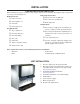
INSTALLATION PRE-INSTALLATION CHECK LIST When installing any system, first make sure the major components are available.
Installation and Service Manual INSTALLATION MII-250 INSTALLATION KIT 9
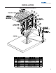
INSTALLATION MII-302 INSTALLATION KIT
Installation and Service Manual INSTALLATION WATER & SYRUP LINES This kit facilitates connecting the unit to a 12-16 line conduit, with one or two carbonated water recirculating systems, and one or two plain water supply lines, and maximum 8 syrup product lines. The Unit is shipped with connecting lines terminating under the unit. It will be necessary to make a 90° turn down through the counter top, to connect to the conduit.
INSTALLATION DRAINAGE OPTIONS The drains for MII Series connects to the drain pan.
Installation and Service Manual INSTALLATION BAG-IN-BOX (B-I-B) SYSTEM NOTE: MII with Valves System Overview This is a simplified schematic to show the basic operation of the beverage system.
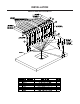
INSTALLATION TOP MOUNTED ICEMAKER REQUIREMENTS 1 Location - Avoid placing the dispenser and/or ice machine near heat sources such as radiators, ovens, refrigeration equipment and direct sunlight. 2 Clearances - Six inch (15.2 cm) clearance on all sides of the icemaker is needed. 3 Front of icemaker to be flush with front of dispenser- The front of the icemaker should be flush with the front of the dispenser, as shown in the drawing above.
Installation and Service Manual INSTALLATION ROCKING CHUTE ICE DELIVERY SWITCH ADJUSTMENT 1 To properly adjust the switch, first unplug the power cord to the unit then remove the merchandiser. This will give you access to the ice delivery switch located on the left side of the rocking chute. 2 Begin by observing the chute by slowly pushing against the rocking chute. When the ice delivery switch clicks, measure the distance from the door stops on the rocking chute bracket to the door.
INSTALLATION BAFFLE FOR MANITOWOC™ CUBERS When installing a Manitowoc™ “S” series Ice Machine on a MII dispenser, a baffle kit is required for proper installation. The baffle kit is designed to prevent ice from lying against the front of the ice machine, and melting down the front of the dispenser. There are two different baffle kits available, one kit is for the 30" wide “S” series ice machine, and the other kit is for the 22" wide “S” series ice machine.
Installation and Service Manual INSTALLATION GENERAL INSTRUCTIONS FOR REMOVAL OF GEAR MOTOR These instructions are provided as a guide for the removal of the gear motor. Depending on the model number of your dispenser, these instructions may vary slightly. 1. Disconnect power from the electric receptacle. 2. Remove all ice from the ice storage bin of the dispenser. 3. Remove the paddle wheel pin from the paddle wheel / agitator assembly inside the dispenser bin. 4.
INSTALLATION MII-250 PLUMBING DIAGRAM MII-302 PLUMBING DIAGRAM
Installation and Service Manual OPERATION UNIT INSPECTION Thoroughly inspect the unit upon delivery. Immediately report any damage that occurred during transportation to the delivery carrier. Request a written inspection report from a claims inspector to document any necessary claim. ICE RECOMENDED FOR DISPENSING MII dispensers are designed to dispense hard, cube ice up to one-inch square. The ice shapes and sizes listed above are recommended for dispensing.
Installation and Service Manual OPERATION MII-250 MEASUREMENTS & SPECIFICATIONS FRONT VIEW BOTTOM VIEW BACK VIEW H K A L M B 3/8"-16 Thread Mounting Holes for optional legs P N C E D F G Unit A B C D E F MII -250 39 " 12.5" 30 " 1.5 " 9.938" 13.5" G H K L 20 " 30.5" 28.375" 22.5" M N 21.688 " 1.75" P 28.
Installation and Service Manual OPERATION MII-302 MEASUREMENTS & SPECIFICATIONS A D L C F K E M G H J N O P Q Unit A B C D E F G H J K L M N O P Q MII -302 33.25" 12.50" 42.75" 1.38" 5.59" 9.10" 12.16" 31.00" 15.78" 28.78" 22.50" .82" 26.97" 30.47" 33.75" 37.16" MII-302 Standard Features Key Switch, Drain Kits, 12" high lighted merchandiser and timed agitation Dimensions 42.75" W x 31" D x 34.25" H (inches) 108.6 W x 78.74 D x 87 H (cm) Shipping Weights 470 lbs. / 213 kgs.
Installation and Service Manual OPERATION MII-250 FOOTPRINT 22
Installation and Service Manual OPERATION MII-302 FOOTPRINT 23
Installation and Service Manual OPERATION CARBONATION The purpose of the carbonator is to take regular tap water at street water pressure (minimum 20 PSI dynamic or flowing pressure) 1/2” water line and increase the water to beverage system pressure (usually 100 PSI). This water is then combined with the CO2 gas. Because the water and gas are at the same pressure, the CO2 will dissolve into the water. Chilling the mixture before dispensing will assist in locking the carbon dioxide into the water.
Installation and Service Manual OPERATION BACK ROOM PACKAGE 1. Incoming tap water - should be at a minimum dynamic pressure of 40 psi and maximum static pressure of 55 psi. 7. Primary pressure regulator - Lowers the CO2 gas pressure, to 100 psi, so the CO2 gas will be at the proper pressure to enter the carbonator regulator. 2. Carbonator Water pump motor - Powers the water pump. The water pump motor is part of the carbonator pump deck. 8. Lowered outgoing pressure - Set for 75 psi.
Installation and Service Manual OPERATION 115V/220V NON ADJUSTABLE AGITATION TIMER The agitation timer on this unit is equipped with test pins. This allows you to test the timer by removing the jumper between the two pins. When the jumper is removed the timer will cycle every 55 seconds if it is operating correctly. If the timer is wired correctly and does not cycle approximately every 55 seconds when the jumper is removed, replacement of the timer may be necessary.
Installation and Service Manual USER MAINTENANCE PREVENTATIVE MAINTENANCE Preventative maintenance is a vital part of keeping your MII dispenser in top condition. Following the guidelines below will assist you in continued trouble free operation of your unit. 1. Conduct daily maintenance of the machine. 2. Perform monthly maintenance of the machine. 3. Perform periodic maintenance and sanitizing of beverage system. 4. Do not overfill the dispenser bin with ice. 5.
Installation and Service Manual USER MAINTENANCE HOW TO DISASSEMBLE FOR CLEANING OR MAINTENANCE 10 Agitator arm and paddlewheel pin: 8. Rotate the agitator arm so the paddle wheel pin handle is pointing up, toward the ceiling. 8 11 9. Prepare agitator pin for removal by removing the stainless steel split ring. 10. Then remove the paddle wheel pin from the hole in the agitator. 11. Push the agitator bar toward the back of the unit until the agitator is free of the paddle wheel hub.
Installation and Service Manual USER MAINTENANCE HOW TO DISASSEMBLE FOR CLEANING OR MAINTENANCE Disassemble the rocking chute: 1. Loosen the two knurled fasteners that hold the merchandiser in place. 2. Remove the merchandiser. 1 3. Remove outer bracket. 2 4. Remove door lock. 5. Remove door. 6. Remove ice chute.
Installation and Service Manual USER MAINTENANCE DAILY CLEANING All cleaning must meet your local health department regulations. The following cleaning instructions are provided as a guide. CAUTION: Use only warm soapy water to clean the exterior of the tower. Do not use solvents or other cleaning agents. Do not pour hot coffee into the drain pan. Pouring hot coffee down the drain pan can eventually crack the drain pan, especially if the drain pan is cold or still contains ice.
Installation and Service Manual USER MAINTENANCE MONTHLY CLEANING Clean and sanitize the ice bin: 1. Unplug unit and remove all ice from the ice bin. solution for at least 10 seconds. 2. Mix a solution of mild detergent to clean the dispenser bin and components. 8. Allow to air dry. Do not rinse. 3. Wash the ice bin using a sponge and the mild detergent solution. 9. Re-assemble parts in the following order: Re-assembling the dispenser parts: • Bin liner 4.
Installation and Service Manual USER MAINTENANCE BEVERAGE SYSTEM CLEANING Sanitize the beverage system at initial start-up as well as regularly scheduled cleaning. The drain pan must be in place under soda valves, to carry away detergent and sanitizing agents that will be flushed through valves. BAG-IN-BOX SYSTEM The procedure below is for the sanitation of one syrup circuit at a time. Repeat to sanitize additional circuits.
Installation and Service Manual USER MAINTENANCE BAG-IN-BOX SYSTEM 10. Connect Bucket 3 to system. 11. Draw sanitizing solution through system until solution is dispensed. 12. Repeat step 11 until all syrup circuits contain sanitizer solution. 13. Allow sanitizer solution to remain in system for 15 minutes. 14. Remove nozzles and diffusers from beverage valves. 15.
Installation and Service Manual EXPLODED VIEWS, PARTS & DIAGRAMS MII-250 EXPLODED VIEW WITH 8 VALVE FLEX MANIFOLD 34
Installation and Service Manual EXPLODED VIEWS, PARTS & DIAGRAMS MII-250 PARTS LIST 35
Installation and Service Manual EXPLODED VIEWS, PARTS & DIAGRAMS MII-302 EXPLODED VIEW WITH TWO 6 VALVE FLEX MANIFOLDS See 302 Carb Water Tubing for more detail 36
Installation and Service Manual EXPLODED VIEWS, PARTS & DIAGRAMS MII-302 PARTS LIST No. Part Number Description 1 0101702 BSHG MUSHROOM INJ MLD 2 00200196 LABEL #1 TUBE ID No.
Installation and Service Manual EXPLODED VIEWS, PARTS & DIAGRAMS MII-302 CARB WATER TUBING 38
Installation and Service Manual EXPLODED VIEWS, PARTS & DIAGRAMS STRIP LID ASSEMBLY (5030332) Optional bin adaptor for MII 200/250 for Manitowoc IB Series or Scotsman Eclipse ice makers.
Installation and Service Manual EXPLODED VIEWS, PARTS & DIAGRAMS MII-302 115V WIRING DIAGRAM 40
Installation and Service Manual TROUBLESHOOTING PROBLEM Dispenser will not dispense ice (and NO SOUNDS are heard when manchine is activated). Dispenser will not dispense ice (motor runs but no ice movement is heard in bin). POSSIBLE CAUSE No power. Check electrical connection. Loose wire in electrical system. Thoroughly check all wire connections. Remove ice from dispenser until Dispenser overloaded with ice. unit will operate. Motor not working.. Check thermally protected motor.
Installation and Service Manual TROUBLESHOOTING PROBLEM Dispensing crushed ice or reduced dispensing speed. POSSIBLE CAUSE Water spillage from ice machine into dispenser bin. Adjust ice maker. Agitation timer Test agitation timer. Bridge of ice sheet is too thick. Adjust ice maker. Paddle wheel area broken or cracked. Replce paddle wheel area. Ice clusters in bin. Break up or remove clusters. Door not fully open. Adjust door. Ice jammed in chute.
Installation and Service Manual 43
INDEX B E M S Back Room Package .............. 25 brixing ....................................... 3 Exploded Views 34, 35, 36, 37, 38, 39, 40 exterior .................................... 30 MBE .......................................... 3 Model Number .......................... 3 modifications ............................. 6 Monthly Cleaning .................... 31 SAFETY ............................... 6, 7 sanitizing ................................... 7 Serial Number ...........................
Manitowoc Beverage Equipment 2100 Future Drive Sellersburg, IN 47172-1868 Tel: 812.246.7000, 800.367.4233 Fax: 812.246.9922 www.manitowocbeverage.com In accordance with our policy of continuous product development and improvement, this information is subject to change at any time without notice.